
User`s manual

20
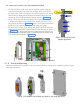
5 Installation of Intraskan dc
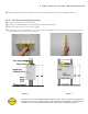
5.5 Scissor Arm Cables Connection
Lay cables flushed along the right
inner side. Carefully pull any
excess length and push the cables
behind the power board.
Figure 26
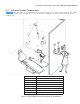
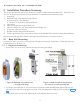
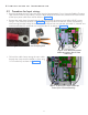
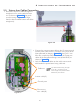
• Connect the communication cable to the J2 connector and
Inverter power cable to the J1 connector using screw driver
(Non-polarised) as shown in Figure 27 . Using a 2.5 mm
allen key, connect the GND wires of both the scissor-arm
cables to the Power Board fixing screw (M3x6 HSHC) as
shown in Figure 27 .
• Lock the scissor-arm cables on the cable mounts avail-
able beside the power board using cable ties.
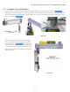
Figure 27
Inverter cable(J1)
Communica-
tion cable(J2)
Ground point
Cable ties
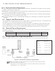
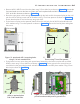
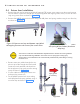
• Route the scissor-arm cables through the
straight-arm till it comes inside the base
unit as shown in Figure 26 (Use guide
wire for routing and guide with finger
from the slots available bottom side of the
straight arm).