
User`s manual

42
8 Service Procedure
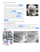
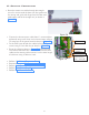
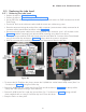
8.2.2.3 Scissor-arm cable connection:
• Using a 2.5mm allen key connect the GND wires(Ring
terminals) of both the Communication & INV power cables
in the Base Unit to the Power Board f ixing screw as shown
in Figure 61 .
• Connect the INV power cable to J1 connector(Non-polar-
ised) using a Jewel screwdriver (holding the connector) as
shown in Figure 61 .
• Connect the communication cable connector to J2 connec-
tor of the power board as shown in the Figure 61 .
• Route the cables as shown in Figure 61 along the right in-
ner side the Bas e Unit. Use new Cable ties to fix the cables
on the existing cable mounts & cut the extra length of cable
ties using a cable tie cutter.
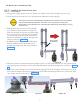
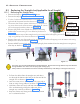
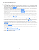
8.2.2.2 HV Tank Assembly:
• Use an ESD wrist strap during HV Tank fixing procedure as below and connect its GND connection to
the HV Tank metal clamp.
• Route the scissor-arm cables as shown in Figure 59 .
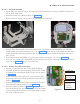
• Take the HV-Tank and fix it to the clamp using the following sequence:-
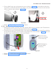
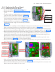
Figure 59 Figure 60
Inverter
cable(J1)
Commu-
nication
cable(J2)
Ground point
Cable ties
Figure 61
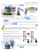
• Using 2.5mm allen key & 5.5mm nut driver fix 3 Hex. Soc. head cap screws(M3X16) with M3 plain
washers & M3 nuts (at the locations 9 to 11 as in Figure 60 ) such that the screw along with M3 plain
washer should be inserted from bottom and nut along with M3 plain washer should be on the top of
the H V Tank.
• Fix 5 button head screws(M3X6) using 2mm allen key(at the locations 1 to 5 as in Figure 60 ).
• Fix 3 Hex. Soc. Head cap screws(M3X6) on the top of the clamp near Tube head arm at the locations
(6 to 8 as in Figure 60 ) using 2.5 mm Allen key.