
User`s manual

54
8.10 Replacing the Scissor Arm cable harness
8.10.1 Removing the Scissor arm cables
• Execute the Steps in "8.2.1.1 Power Off:".
• Execute the steps in "8.2.1.2 Tube Head Cover Removal:".
• Execute the steps in "8.2.1.3 Base Unit Cover removal:".
• Execute the steps in "8.2.1.4 Scissor-arm cables disconnecting".
• Execute the steps in "8.2.1.5 HV Tank removal".
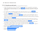
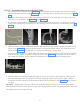
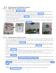
• Keep the Vertical Arm of the scissor arm in Vertical position and Horizontal Arm in horizontal position
as shown in Figure 90 .
• Remove the rubber plugs of the wire cup using tweezer and then remove the wire cup on the L-arm by
removing the 2 M3X25 screws using 2.5mm allen key as shown in Figure 91.
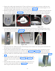
• Remove the rubber Cable cover on the L-Arm by pulling out as shown in Figure 92 .
Figure 90 Figure 91
Figure 92
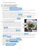
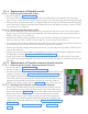
• Remove all the four scissor-arm end caps by opening the
caps. Do not remove the rubber part shown in Figure 93 .
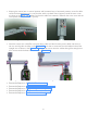
• Remove the bottom caps of straight arm by removing M3x6
self tapping CSK head screws using screw driver. Remove the
side cap of the tube head arm.
• Without removing the Scissor arm, first remove the Inverter
Power cable from the scissor arm.
• Next remove the Communication cable (with connector) from
the scissor arm. If required put a tape on the cable ends for
easy removal. Use guide wire if required to pull the cable from
the Straight Arm through the slot.
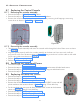
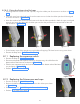
• Remove the base unit cover fixing clamp by removing 2 M3x6
HSHC screws using 2.5mm allen key.
Figure 93