
User`s manual

60
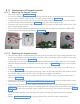
8.14 Replacement of Doorbell switch:
8.14.1 Removing the Door bell switch:
• Execute the steps in “8.2.1.1 Power Off:”.
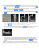
• Pull out the Dummy Logo assembly from the slot on the Door bell switch assembly and remove the
front cover by removing 4 M3×6 HSHC Screws using 2.5mm Allen key. Keep the removed parts aside.
• Disconnect the communication cable coming from the base unit from the Console extension board-Ex-
ternal. Remove the Console extension board-External from the wall plate by removing 4 M3×6 HSHC
screws using 2.5mm Allen key.
8.14.2 Replacing the Door bell switch:
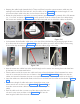
• Take the new Door bell switch assembly from the packing box and pull out the Dummy Logo assem-
bly from the slot on the Door bell switch assembly and remove the front cover by removing 4 M3×6
HSHC screws using 2.5mm Allen key.
• Keep the removed parts aside carefully. Remove the Console extension board-External from the wall
plate by removing 4 M3×6 HSHC screws at the four corners using 2.5mm allen key.
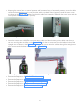
• If required remove the old wall plate from wall 2 M6×30 lag bolts using 8mm box spanner and fix the
new wall plate on the wall with 2 M6×30 lag bolts using 8mm box spanner.
• Take the new Console extension board-External and fix it to the wall plate with 4 M3×6 HSHC screws
using 2.5mm Allen key.
• Connect the communication cable to the appropriate connector by referring the configuration connec-
tion diagrams in Section “5.8 Intraskan DC Console configurations:”.
• Take the new front cover and fix it on the wall plate with 4 M3×6 HSHC screws using 2.5mm Allen
key. Fix the Dummy Logo assembly in the slot and switch on the unit and give exposures from the exter-
nal switch.
8.15 Replacement of Console extension board-internal
8.15.1 Removing the Console extension board-internal
• Execute the steps in “8.2.1.1 Power Off:”.
• Execute the steps in “8.2.1.3 Base Unit Cover removal:”.
• Disconnect the external communication cable coming from the wall from the
respective connector (Refer“5.8 Intraskan DC Console configurations:”) on
the Console extension board-internal and disconnect the cable from con-
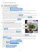
nector PB/J4 of the Console extension board-internal. Remove the Console
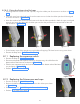
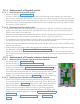
extension board-internal from the base unit plate by removing 4 M3×6
HSHC screws at the locations shown in Figure 118 using 2.5mm allen key.
8.15.2 Replacing the Console extension board-internal:
• Take the new Console extension board-internal from the packing box and
fix it in the base unit with 4 M3×6 HSHC screws using 2.5mm allen key at
the locations shown in Figure 118 . Connect the cable coming from power
board to the PB/J4 connector on the Console extension board-internal.
• Connect the communication cable coming from wall to the appropriate
connector on the Console extension board-Internal board by referring the
configuration connection diagrams in Section “5.8 Intraskan DC Console
configurations:”.
• Execute the steps in "5.9 Base unit cover fixing:" and "5.12 Power On
Check:".
Figure 118