
User`s manual


61
8.16 Replacing the Input switch
8.16.1 Removing the Input Switch
• Execute the Steps in "8.2.1.1 Power Off:".
• Execute the steps in "8.2.1.3 Base Unit Cover removal:".
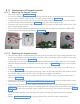
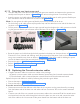
• Disconnect the “Live(Blue) and Neutral(Black) wires(Ring termi-
nals) of switch” from the terminal block fixed on the power board
clamp using phillips screw driver as shown in Figure 119 .
• If required disconnect the GND(ring terminal) wire from the GND
terminal on power board plate located just below the switch
by removing the M3X6 HSHC screw using 2.5mm allen key as
shown in the Figure 119 .
• Remove the power board clamp from the base unit by removing 1
M3X6 HSHC Screw on top side of the power board using 2.5mm
allen key and 2 M3X8 HSHC screws, plain washers and Jam nuts
(screws will be inserted from rear side and nut with washer to
be fixed from front side) using 2.5mm allen key and 5.5mm nut
driver at the locations shown in Figure 119 .
Figure 119
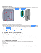
Figure 120
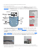
Figure 121
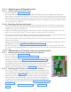
• Disconnect the wires(Pin terminals) from the J5 connector on the power board using a Jewel screw
driver as shown in Figure 120 (Live=Blue & Neutral=Black).
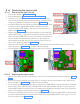
• Pull out defective switch from the base unit rear cover as shown in Figure 121 .
8.16.2 Replacing the Input switch
• Take the new switch and fix it in the base unit rear cover by inserting from outside as shown in Figure
121 .
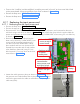
• Connect the switch wires(Pin terminals) to the J5 connector on the power board using a Jewel screw
driver as shown in Figure 120 (Live=Blue & Neutral=Black).
• Fix the power board clamp from the base unit by fixing 1 M3X6 HSHC Screw on top side of the power
board using 2.5mm allen key and 2 M3X8 HSHC screws, plain washers and Jam nuts (screws to be
inserted from bottom rear side and nut with washer to be fixed from front side) using 2.5mm allen key
and 5.5mm nut driver at the locations shown in Figure 119 .
• Connect the GND(ring terminal) wire to the GND terminal along with the other GND wire(If removed)
on power board plate located just below the switch by fixing the M3X6 HSHC screw using 2.5 mm al-
len key as shown in the Figure 119 .