
System Manual

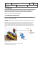
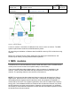
Table Of Contents

Page 1 of 3
Document ID
VERSION
DATE
SCDOC-74-6
TITLE
MDS system manual
V0.4 2019-01-07
AUTHOR
DOCUMENT RESPONSIBLE
APPROVED BY
Henrik Sihm
Construction Tools PC AB
1 OVERVIEW
MDS system measures distance between its nodes, which consists of three parts; one
MDS-anchor mounted inside a remote control called MC11-OPS and two MDS-tags
placed in the front and rear in a moving machine to which distance is measured.
MDS is an acronym for Machine Distance Sensor.
2 OPERATING DESCRIPTION
MDS uses Ultra-Wide Band (UWB) radio technology to measure ToF (Time of Flight),
which is then converted to distance.
All MDS are identical in terms of electronic HW and SW, with the exception of anchor and
tag setting.
MDS distance data is used for perimeter fencing around dangerous machines as seen in
picture below. Safe perimeter used is minimum 2m. If the remote control is within 2m
from the machine, the ECU (main computer inside the machine) will stop the machine for
operator safety. The ECU is continously receiving distance data from MDS-tag via CAN
bus
Figure 1: Real life setup.
MDS measures distance at 2Hz with +/-10cm accuracy.
It has a range of 30m line of sight.