
System Manual

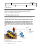
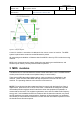
Table Of Contents

Page 2 of 2
Document ID
VERSION
DATE
SCDOC-74-6
TITLE
MDS system manual
V0.4 2019-01-07
AUTHOR
DOCUMENT RESPONSIBLE
APPROVED BY
Henrik Sihm
Construction Tools PC AB
Figure 2: Principle diagram.
Control of machine is transmitted via Bluetooth from remote control of machine. The MDS
system is paired at the same time as the Bluetooth is paired.
All processing and validation of distance data from MDS is done by ECU inside the moving
machine.
MDS is only a support sensor system, helping the user staying at a safe distance, and
should only be used by correctly trained machine operators.
The MDS-anchor is mounted inside the remote control called MC11-OPS. The MDS-anchor
receive power from the remote control (either battery or control cable).
3 MDS modules
There are two MDS-tags placed inside casings, using connectors for installation in the
machine. These units are called MDS and they are placed in the front and rear of the
machine. The operating distance to the machine is minimum 2m.
NOTE:
This equipment has been tested and found to comply with the limits for a Class A
digital device, pursuant to Part 15 of the FCC Rules. These limits are designed to provide
reasonable protection against harmful interference when the equipment is operated in a
commercial environment. This equipment generates, uses, and can radiate radio frequency
energy and, if not installed and used in accordance with the instruction manual, may cause
harmful interference to radio communications. Operation of this equipment in a residential
area is likely to cause harmful interference in which case the user will be required to correct
the interference at his own expense.