
Installation Instructions


Page 6
(Continued)
Function
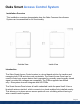
This power supply controller can control electric locks by switching the signal from access
controllers or power supply output DC12V directly. It can reduce overload controller, adjust
electric lock to on or off mode, adjust the open delay time, open key.
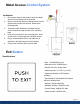
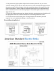
Wiring Diagram for Installation:
Start by removing 2 silver screws to remove the power supply controller cover. There are 4 screw
holes on the bottom part of the power supply controller. Screw in 2 or 4 screws depending on how
the power supply controller will be orientated. It is recommended that the power supply controller
is mounted flush against the wall. (Refer to Wiring Diagram section for wiring instructions)
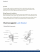
Electro-magnetic Lock Bracket
Bracket Main Components
Plate