
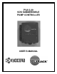
User`s manual


12/06/99 5
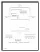
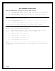
WIRE TERMINAL DESCRIPTIONS
WITH DIP SWITCH #6 ON: High water cut-off (Tank fill-up)
1 LO LOW WATER LEVEL SENSOR turns the pump on.(Mount an E-1s electrode 2”
above the ground sensor.)
2 Hi HIGH WATER LEVEL SENSOR turns the pump off. (Mount an E-1s brass
electrode at the desired turn-off point.)
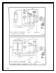
WITH DIP SWITCH 45 ON: Low water cut-off
1 LO LOW WATER LEVEL SENSOR turns the pump off. (Mount an E-1s electrode
2” above the ground sensor.)
2 Hi HIGH WATER LEVEL SENSOR turns the pump on. (Mount an E-1s brass
electrode below the static water level at the desired turn-on point.)
3 GN GROUND OR COMMON WATER SENSOR must be in the water at all times.
(Mount an E-1s electrode 2” above the pump-)
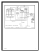
3 & 4 REMOTE ON-OFF CIRCUIT is used to turn the pump on and off from a
remote location. (Short the two terminals to turn the pump off.)
5 PV- NEGATIVE WIRE from the PV array.
6 LD- NEGATIVE WIRE to the pump or load.
7 LD+ POSITIVE WIRE to the pump or load.
8 PV+ POSITIVE WIRE from the PV array.
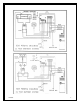
*NOTE
If the low water cut-off circuit is not being used, switch #5 must be in
the off position and switch #6 must be in the on position for the controller to
work properly.