
Installation guide

Installation
1–4 975-0639-01-01 Rev A
This guide for use by qualified personnel only
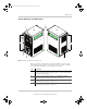
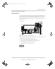
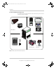
5 AC line terminals. See “AC and DC Terminals, Network and
Communication Ports Panel” on page 1–5.
6 Two variable-speed cooling fans maintain a cool internal temperature
of critical components. The two fans control airflow through the
transformer and power compartments of the unit. Ensure at least
10" (254 mm) of clearance for proper ventilation.
7 Mounting holes for permanent installation. See “Step 2: Mounting the
Inverter/Charger” on page 1–19.
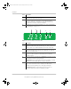
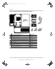
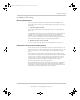
Figure 1-3 Front Panel Buttons and Status LEDs
Item Description
1Inv Enable button is used to enable and disable inverter mode.
“Enabled” is different from the inverter being “on”. When enabled, the
inverter can be on or off. When disabled, the inverter is always off.
2 Clear Fault | Reset button is used to clear any detected faults if
pressed momentarily. If held down for more than three seconds, the
unit will reset (reboot) itself.
3Fault | Warning LED illuminates steadily if a fault is detected (a fault
detection condition) and flashes intermittently when a warning
condition is active.
4 When AC is present and qualified, the AC IN LED will illuminate steadily
indicating also that AC is passing through.
Charging LED flashes intermittently when the Conext SW is in charge
mode and is producing DC output to charge your batteries.
5 The Inv Enabled LED illuminates steadily when invert mode is enabled.
If AC is present and invert mode is enabled, this LED remains
illuminated even though AC power is being passed through.
Gen Support LED flashes intermittently when the inverter is in
generator support mode and is assisting the generator.
Item Description
12
34
5
ConextSW-NA-InstallationGuide.book Page 4 Thursday, December 20, 2012 2:05 PM