
Installation guide


Installation
1–22 975-0639-01-01 Rev A
This guide for use by qualified personnel only
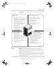
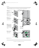
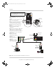
Figure 1-11 Conext SW AC INPUT and OUTPUT Connections
L1
L2
N
AC Cable
(3)
(4)
(1)
Make the wiring connections to the AC
source main panel.
(2) Route the AC cable to the inverter/
charger.
(3) Remove the wiring compartment cover
panel on the inverter/charger.
(4) Remove the AC knockouts from the side
or bottom (or both). Do not leave the
knockout inside the wiring compartment.
(5) Install a strain-relief clamp in the AC
knockout.
(6) Route the AC cable through the AC
knockout and inside the wiring
compartment.
(7) Connect Line1 to L1, Line 2 to L2, Neutral
to N, ground to . If solid ground wire is
being used, the wire can be connected
directly under the screw heads. If stranded
ground wire is being used, ring terminals
must be used.
(8) Tighten the terminal
screws. Leave a service
loop in the wires inside the
wiring box.
(9) Make the wiring
connections to the inverter
load panel.
(10) Replace the wiring
compartment cover panel
on the inverter/charger.
side AC
knockouts
bottom AC
knockouts
to Inverter
AC INPUT
strip at least
2” (50mm)
strip at least
1/2” (13mm)
Inverter Load Panel
AC Source
Main Panel
NOTE: Make the connections to the AC INPUT
side first (steps (3) to (8)) then the AC OUTPUT
side (steps (4) to (9)). Finish with step (10).
(9)
(1)
(2)
Transfer switch
ConextSW-NA-InstallationGuide.book Page 22 Thursday, December 20, 2012 2:05 PM