ConextSWEUROInstallationGuide.book Page i Wednesday, December 5, 2012 10:55 AM Conext™ SW Inverter Charger Conext SW 2524 230 (865-2524-61) Conext SW 4024 230 (865-4024-61) Installation Guide TM www.schneider-electric.
ConextSWEUROInstallationGuide.
ConextSWEUROInstallationGuide.book Page i Wednesday, December 5, 2012 10:55 AM Conext SW Inverter Charger Conext SW 2524 230 (865-2524-61) Conext SW 4024 230 (865-4024-61) Installation Guide www.schneider-electric.
ConextSWEUROInstallationGuide.book Page ii Wednesday, December 5, 2012 10:55 AM Copyright and Contact Copyright © 2012 Schneider Electric. All Rights Reserved. All trademarks are owned by Schneider Electric Industries SAS or its affiliated companies.
ConextSWEUROInstallationGuide.book Page iii Wednesday, December 5, 2012 10:55 AM About This Guide Purpose The purpose of this Installation Guide is to provide explanations and procedures for installing the Conext SW Inverter/Charger to a main AC power source such as an AC generator for off-grid application or AC mains (main power grid) for power backup application. Scope The Guide provides safety and installation guidelines as well as information on tools and wiring.
ConextSWEUROInstallationGuide.book Page iv Wednesday, December 5, 2012 10:55 AM About This Guide Conventions Used The following conventions are used in this guide. DANGER DANGER indicates an imminently hazardous situation, which, if not avoided, will result in death or serious injury. WARNING WARNING indicates a potentially hazardous situation, which, if not avoided, can result in death or serious injury.
ConextSWEUROInstallationGuide.book Page v Wednesday, December 5, 2012 10:55 AM Important Safety Instructions READ AND SAVE THESE INSTRUCTIONS - DO NOT DISCARD DANGER ELECTRICAL SHOCK AND FIRE HAZARD Installation must be done by qualified personnel to ensure compliance with all applicable installation and electrical codes and regulations. Instructions for installing the Conext SW are provided here for use by qualified installers only.
ConextSWEUROInstallationGuide.book Page vi Wednesday, December 5, 2012 10:55 AM Safety DANGER ELECTRIC SHOCK HAZARD • For indoor use only. This inverter/charger is designed for off-grid, solar, backup, and hybrid applications. • Do not operate the inverter/charger if it has been damaged in any way. • Do not operate the inverter/charger with damaged or substandard wiring. Wiring must be done by qualified personnel to ensure compliance with all applicable installation codes and regulations.
ConextSWEUROInstallationGuide.book Page vii Wednesday, December 5, 2012 10:55 AM Safety Precautions When Working With Batteries Important: Battery work and maintenance must be done or supervised by qualified personnel knowledgeable about batteries to ensure compliance with battery handling and maintenance safety precautions. WARNING ENERGY AND FIRE HAZARD • Always wear proper, non-absorbent gloves, complete eye protection, and clothing protection.
ConextSWEUROInstallationGuide.book Page viii Wednesday, December 5, 2012 10:55 AM Safety CAUTION CHEMICAL HAZARD • Never allow battery acid to drip when reading specific gravity or filling battery. • Make sure the area around the battery is well ventilated. • Make sure the voltage of the batteries matches the output voltage of the inverter/charger.
ConextSWEUROInstallationGuide.book Page ix Wednesday, December 5, 2012 10:55 AM Safety Product Recycling Do not dispose of this product with general household waste! Electrical appliances marked with the symbol shown must be professionally treated to recover, reuse, and recycle materials, in order to reduce negative environmental impact.
ConextSWEUROInstallationGuide.
ConextSWEUROInstallationGuide.
ConextSWEUROInstallationGuide.
ConextSWEUROInstallationGuide.
ConextSWEUROInstallationGuide.
ConextSWEUROInstallationGuide.
ConextSWEUROInstallationGuide.
ConextSWEUROInstallationGuide.book Page 1 Wednesday, December 5, 2012 10:55 AM 1 Installation The following topics will be covered in this chapter.
ConextSWEUROInstallationGuide.
ConextSWEUROInstallationGuide.book Page 3 Wednesday, December 5, 2012 10:55 AM Materials List Conext SW Front and Side Panels 1 2 TOP TOP 3 8 8 6 4 7 5 Figure 1-2 Conext SW Front and Side Panels Before you begin to operate the Conext SW after installation, review the front panel features shown in Figure 1-3 and described in the next table. A detailed view of the lights and buttons on the front panel is also shown.
ConextSWEUROInstallationGuide.book Page 4 Wednesday, December 5, 2012 10:55 AM Installation Item Description 5 AC line terminals. See “AC and DC Terminals, Network and Communication Ports Panel” on page 1–5. 6 Manual reset button for the built-in 30-amp AC input circuit breaker. 7 Two variable-speed cooling fans maintain a cool internal temperature of critical components. The two fans control airflow through the transformer and power compartments of the unit.
ConextSWEUROInstallationGuide.book Page 5 Wednesday, December 5, 2012 10:55 AM Materials List Conext SW AC/DC/Ports Side Panel 3 1 7 b a 4 2 5 6 8 9 Figure 1-4 AC and DC Terminals, Network and Communication Ports Panel Item 1 Description Battery Positive (+) DC terminal connects to the positive battery cable (red). Install a DC terminal cover (supplied) over the terminal. Battery Negative (–) DC terminal connects to the negative battery cable (black).
ConextSWEUROInstallationGuide.book Page 6 Wednesday, December 5, 2012 10:55 AM Installation Conext SW Supplied Accessories 1 2 3 4 Figure 1-5 Supplied Accessories NOTE: If any of the supplied accessories are missing, contact customer service for replacement. See “Contact Information www.schneider-electric.com” on page ii. Item Description 1 Two DC terminal covers prevent accidental contact with the DC cable connectors after installation.
ConextSWEUROInstallationGuide.book Page 7 Wednesday, December 5, 2012 10:55 AM Installation Information Installation Information Before You Begin the Installation Before beginning your installation: • Read the entire Installation Guide so you can plan the installation from beginning to end. • Assemble all the tools and materials you require for the installation. • Review the Important Safety Instructions on page v. • Be aware of all safety and electrical codes which must be met.
ConextSWEUROInstallationGuide.book Page 8 Wednesday, December 5, 2012 10:55 AM Installation Xanbus Network System Xanbus System The Xanbus system includes the Conext SW and other Xanbus-enabled devices. The Conext SW is the device in a Xanbus system that typically provides network power—500 mA at 12 VDC. All of the Xanbus-enabled devices, such as the Conext SW, the SCP, and the AGS are able to communicate their settings and activity to each other.
ConextSWEUROInstallationGuide.
ConextSWEUROInstallationGuide.book Page 10 Wednesday, December 5, 2012 10:55 AM Installation Installation Planning Planning Preparations This section provides information to help plan for a basic installation of the Conext SW. There are two key factors that will have a major impact on system performance. 1. Size and Length of DC Cables To select the appropriate size and length of DC cables, see “DC Cabling” on page 1–13.
ConextSWEUROInstallationGuide.book Page 11 Wednesday, December 5, 2012 10:55 AM Installation Planning AC, DC, and Network Components The illustration below shows the different components that can go into a Conext SW inverter/charger installation.
ConextSWEUROInstallationGuide.book Page 12 Wednesday, December 5, 2012 10:55 AM Installation The illustration below shows which components you may need before you begin your installation. DC Components Xanbus Network Components • 24-volt battery or batteries, see “DC Component -Batteries” on page 1–13. • System Control Panel (SCP) • Automatic Generator Start (AGS) • DC-rated fuse and/or circuit breaker, see “DC Disconnects and Overcurrent Devices” on page 1–14.
ConextSWEUROInstallationGuide.book Page 13 Wednesday, December 5, 2012 10:55 AM Installation Planning Size of AC Input Wiring IMPORTANT: Wire size must be coordinated with the overcurrent protection provided ahead of the wire involved, in accordance with the electrical codes or regulations applicable to your installation. Therefore, the wiring used between the main AC source panel’s circuit breaker and the inverter/charger AC INPUT must be sized to match the input breaker rating.
ConextSWEUROInstallationGuide.book Page 14 Wednesday, December 5, 2012 10:55 AM Installation Table 1-2 Recommended Battery Cablea Sizes Model Cable Length < 1.5 m Maximum Current (A) Cable Length 1.5 to 3.0 m Conduit / (Free Air) SW 2524 230 120 50 mm2 (25 mm2) SW 4024 230 200 240 mm2 (120 mm2) 300 mm2 (150 mm2) 70 mm2 (35 mm2) a.70°C thermoplastic insulated cable IMPORTANT: Using a smaller gauge cable or a longer cable may cause the inverter to shut down under heavy load.
ConextSWEUROInstallationGuide.book Page 15 Wednesday, December 5, 2012 10:55 AM Installation Planning Unpacking and Inspecting the Conext SW Inverter/Charger CAUTION HEAVY LOAD HAZARD Do not lift the unit by yourself. Use two people to lift and mount the unit. Always use proper lifting techniques during installation to prevent injury. Failure to follow these instructions can result in injury.
ConextSWEUROInstallationGuide.book Page 16 Wednesday, December 5, 2012 10:55 AM Installation Installation Tools and Materials Tools You will need the following tools to install the Conext SW and the battery temperature sensor. ❐ Wire stripper ❐ Crimping tools for fastening lugs and terminals on DC cables ❐ Phillips screwdriver: #2 bit ❐ Slot screwdriver (6mm wide blade max.
ConextSWEUROInstallationGuide.book Page 17 Wednesday, December 5, 2012 10:55 AM Inverter/Charger Installation Inverter/Charger Installation Overview This section provides detailed information on installing the Conext SW.
ConextSWEUROInstallationGuide.book Page 18 Wednesday, December 5, 2012 10:55 AM Installation Step 1: Choosing a Location for the Inverter/Charger WARNING FIRE HAZARD For indoor use only. Do not install and/or operate in compartments containing flammable materials or in locations that require ignition-protected equipment. Do not cover or obstruct the ventilation openings. Do not install this unit in a compartment with limited airflow.
ConextSWEUROInstallationGuide.book Page 19 Wednesday, December 5, 2012 10:55 AM Inverter/Charger Installation TIP: Align the mounting holes in the center of wall studs. If necessary, fasten a plywood board first to a wall with non-standard-spaced wall studs. Then mount the inverter/charger on the plywood board. 406mm standardspaced wall studs. (1) Place the installation bracket flat on the wall (or plywood) and mark the positions of the mounting holes on the wall. (2) 5 7/8 in. 149.
ConextSWEUROInstallationGuide.book Page 20 Wednesday, December 5, 2012 10:55 AM Installation Step 3: Connecting the AC Input and AC Output Wires DANGER ELECTRICAL SHOCK AND FIRE HAZARD • Make sure wiring being connected to the inverter/charger is disconnected (physically or by opening and locking out the breaker) from all electrical sources before handling. All wiring must be done in accordance with local and national electrical wiring codes.
ConextSWEUROInstallationGuide.book Page 21 Wednesday, December 5, 2012 10:55 AM Inverter/Charger Installation NOTE: Make the connections to the AC INPUT side first (steps (3) to (8)) then the AC OUTPUT side (steps (4) to (9)). Finish with step (10). (1) Make the wiring connections to the AC source main panel. (2) Route the AC cable to the inverter/ (3) side AC knockouts charger. (3) Remove the wiring compartment cover panel on the inverter/charger.
ConextSWEUROInstallationGuide.book Page 22 Wednesday, December 5, 2012 10:55 AM Installation Step 4: Connecting the DC Cables DC Connection Precautions WARNING ELECTRICAL SHOCK HAZARD Connect and disconnect DC wiring only after opening and locking out the disconnect switches or breakers at all AC and DC sources. Failure to follow these instructions can result in death or serious injury.
ConextSWEUROInstallationGuide.book Page 23 Wednesday, December 5, 2012 10:55 AM Inverter/Charger Installation Connecting the DC Cables to the Inverter/Charger WARNING FIRE HAZARD • Use only appropriately sized copper cable. Loose connections, improper connections, and under-rated cables will overheat. • Make sure the supplied nuts on the inverter/charger are tightened to a torque of 13.5–14.9 Nm. Torque all other connections to the manufacturer’s specifications.
ConextSWEUROInstallationGuide.book Page 24 Wednesday, December 5, 2012 10:55 AM Installation (1) Route the DC cables from the battery bank to the inverter/charger. (2) Install a DC fuse (a) and DC disconnect switch (b) or a DC circuit breaker (c) between the inverter/charger and the battery on the positive cable. (3) Open and lockout the DC disconnect switch or DC circuit breaker. (4) Connect one connector on the POSITIVE (+) cable to the BATTERY POSITIVE terminal on the inverter/charger.
ConextSWEUROInstallationGuide.book Page 25 Wednesday, December 5, 2012 10:55 AM Inverter/Charger Installation Step 5: Connecting the BTS and Xanbus-enabled Components WARNING ELECTRICAL SHOCK HAZARD Connect and disconnect DC wiring only after opening and locking out the disconnect switches or breakers at all AC and DC sources. Failure to follow these instructions can result in death or serious injury.
ConextSWEUROInstallationGuide.book Page 26 Wednesday, December 5, 2012 10:55 AM Installation (1) Install the BTS sensor on the battery. Method (a) involves mounting the sensor to the (3) Connect the Xanbus-enabled devices negative battery post which allows the internal battery temperature to be sensed providing the most accurate results. using the provided network cable. Terminate each end of the network with a network terminator (c) and (d).
ConextSWEUROInstallationGuide.book Page 27 Wednesday, December 5, 2012 10:55 AM Inverter/Charger Installation Step 6: Performing Checks Prior to Initial Start-Up Before testing your installation, ensure these conditions are met. ❐ AC earth are properly installed. ❐ AC input connections and AC output connections are wired correctly on the terminal block and not reversed.
ConextSWEUROInstallationGuide.book Page 28 Wednesday, December 5, 2012 10:55 AM Installation Testing in Invert Mode To test the Conext SW in invert mode, using a 100 watt light bulb as the test load: 1. Close the DC disconnect switch or the DC circuit breaker to supply DC power to the Conext SW. Wait for the LEDs on the front panel to flash on and off, indicating that the unit is successfully initializing (10 to 30 seconds). The LEDs will turn off after initialization.
ConextSWEUROInstallationGuide.book Page 29 Wednesday, December 5, 2012 10:55 AM Multiple Unit Configuration Multiple Unit Configuration The Conext SW inverter/chargers supports multiple unit configuration to increase power output. This gives the system engineer and/or installer more options to work with when tailoring a system to meet load demands. Multiple inverter/ chargers of different power levels can be installed in a system as stand alone or in parallel.
ConextSWEUROInstallationGuide.book Page 30 Wednesday, December 5, 2012 10:55 AM Installation DC Connections for Multiple Unit Configuration Individual overcurrent devices are to be used between the battery positive and each inverter. Keep cable lengths to the two inverter/chargers the same in order to balance cable losses. The battery cable between the two inverter/chargers should not exceed 30 cm in length. Connect the units as follows: 1. Connect the positive cables.
ConextSWEUROInstallationGuide.book Page 31 Wednesday, December 5, 2012 10:55 AM Multiple Unit Configuration Neutral Wiring for Inverters in Multiple Unit Configuration In a multiple unit configuration, connect the two AC input neutrals together at the main distribution panel and the two AC output neutrals at an isolated neutral location in the inverter AC distribution panel.
ConextSWEUROInstallationGuide.book Page 32 Wednesday, December 5, 2012 10:55 AM Installation Configuring the System for Multiple Unit Operation Verify all DC and AC connections. Check Xanbus network connections and ensure that terminators are installed at devices at each end of the network. The simplest system includes a Xanbus SCP, the two multi-unit-configured Conext SW inverter/chargers, and two Xanbus terminators.
ConextSWEUROInstallationGuide.book Page 33 Wednesday, December 5, 2012 10:55 AM Multiple Unit Configuration Search Mode Operation in Multiple Unit Configuration When two inverter/chargers are configured, search mode behavior on the Slave unit is modified and is dependent on how much total load is on the system. Disabling Search Mode on the Master Unit Search mode on the Master unit will not function properly.
ConextSWEUROInstallationGuide.book Page 34 Wednesday, December 5, 2012 10:55 AM Installation Battery Information Battery Bank Sizing Battery capacity Battery size or capacity is just as important as the battery type selected for use with the Conext SW. The batteries are the most important part of your system, so it is recommended that you purchase as much battery capacity as possible. A large battery will extend running time and ensure that your inverter/charger delivers full rated surge.
ConextSWEUROInstallationGuide.book Page 35 Wednesday, December 5, 2012 10:55 AM Battery Information Estimating Battery Requirements Calculating Battery Size Step 1: Compute Amp-hours For each appliance, compute the number of amp-hours that will be used between charging cycles, as follows: 1. Obtain the wattage. If the wattage is marked on the nameplate rating, use that. Otherwise, multiply the marked voltage and amperage: WATTS = VOLTS × AMPS. 2.
ConextSWEUROInstallationGuide.
ConextSWEUROInstallationGuide.book Page 37 Wednesday, December 5, 2012 10:55 AM Battery Information Restrictions on Motor Size An appliance may require three to six times its normal running current in order to start. The Conext SW can handle surges up to twice its rated amount (surge current) for five seconds. For example, the model Conext SW 4024 230 is rated as having a maximum continuous output current of 16 amps. Its surge current is twice this value, which is 32 amps.
ConextSWEUROInstallationGuide.book Page 38 Wednesday, December 5, 2012 10:55 AM Installation Battery Cabling and Hook-up Configurations Several smaller batteries can be connected to create a battery bank of substantial size. You can connect batteries in three ways: in parallel, series, or series-parallel. To make a larger battery bank, connect individual batteries with heavy cables. The actual size of the cable depends on whether the batteries are connected in parallel or series.
ConextSWEUROInstallationGuide.book Page 39 Wednesday, December 5, 2012 10:55 AM Battery Information Battery Series Connection When batteries are connected with the positive terminal of one battery to the negative terminal of the next battery, they are connected in series. In a series configuration, the battery bank has the same Ah rating of a single battery, but an overall voltage equal to the sum of the individual batteries. See below.
ConextSWEUROInstallationGuide.
ConextSWEUROInstallationGuide.book Page 1 Wednesday, December 5, 2012 10:55 AM 2 Specifications NOTE: Specifications are subject to change without prior notice.
ConextSWEUROInstallationGuide.
ConextSWEUROInstallationGuide.book Page 3 Wednesday, December 5, 2012 10:55 AM Charger Specifications Charger Specifications NOTE: All charging specifications are at nominal conditions: ambient temperature of 25 °C, 230 VAC, 50 Hz input, unless otherwise specified. DC Output SW 2524 230 SW 4024 230 Maximum output current 65 A 90 A Nominal output voltage 24 VDC 24 VDC Charging output voltage operation range 12.0–32.0 VDC 12.0–32.
ConextSWEUROInstallationGuide.book Page 4 Wednesday, December 5, 2012 10:55 AM Specifications AC Transfer Specifications NOTE: All transfer specifications are at nominal conditions: ambient temperature of 25 °C, 230 VAC, 50 Hz input, unless otherwise specified.
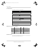
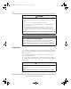
ConextSWEUROInstallationGuide.book Page 5 Wednesday, December 5, 2012 10:55 AM Regulatory W 3750 3500 3250 3000 2750 2500 2250 2000 1750 1500 Full power at ambient SW 4024 230 3500W 3000W SW 2524 230 2500W 2000W -20 -10 0 5 10 15 20 25 30 35 40 45 50 55 60 °C Figure 2-1 Output Power versus Temperature Derating Graph NOTE: The charger output current does not derate up to 60 °C.
ConextSWEUROInstallationGuide.
ConextSWEUROInstallationGuide.book Page 1 Wednesday, December 5, 2012 10:55 AM 3 Wiring Diagrams “Wiring Diagrams” illustrate the most basic BOS configurations and are for reference only. Specific installations may require additional equipment to meet national or local electric codes. Ensure all safety requirements are strictly followed. For...... See....
ConextSWEUROInstallationGuide.
ConextSW_IG_3_Wiring Diagrams_11x16p6.fm Page 3 Wednesday, December 5, 2012 10:59 AM Single-Inverter System (Off-Grid/Power Backup) Single-Inverter System (Off-Grid/Power Backup) DANGER ELECTRICAL SHOCK AND FIRE HAZARD Accessories Communication System Control Panel Automatic Generator Start (optional) (optional) Conext SW DC Switchgear Conext SW DC Switchgear Fault/ Warning Battery 20. 4 A 53.
ConextSW_IG_3_Wiring Diagrams_11x16p6.fm Page 4 Wednesday, December 5, 2012 10:59 AM ACCESSORIES Communication Cable (Category 5) BTS Conext SW Inverter/Charger Conext SW DC Switchgear Xanbus DC Disconnect Xanbus Network Terminator System Control Panel (optional) Automatic Generator Start (optional) Conext ComBox (optional) Power Fault/Warning Battery Positive System Status Battery 20.4 A 53.
ConextSW_IG_3_Wiring Diagrams_11x16p6.fm Page 5 Wednesday, December 5, 2012 10:59 AM Single-Inverter System Renewable Energy (Solar) Single-Inverter System Renewable Energy (Solar) DANGER ELECTRICAL SHOCK AND FIRE HAZARD Accessories Communication System Control Panel Automatic Generator Start (optional) (optional) Conext SW DC Switchgear Renewable Energy Fault/ Warning Battery 20. 4 A 53.
ConextSW_IG_3_Wiring Diagrams_11x16p6.fm Page 6 Wednesday, December 5, 2012 10:59 AM ACCESSORIES Communication Cable (Category 5) BTS Conext SW Inverter/Charger Conext SW DC Switchgear Solar Charge Controller System Control Panel (optional) Xanbus Renewable Energy Photovoltaic DC Disconnect Ente r Standby Generator On Network Fault Exit Automatic Generator Start Stacking Xanbus Network Terminator REM Battery Negative BTS PV – System Status Battery 20.4 A 53.
ConextSW_IG_3_Wiring Diagrams_11x16p6.fm Page 7 Wednesday, December 5, 2012 10:59 AM Dual-Inverter System Renewable Energy (Solar) Dual-Inverter System Renewable Energy (Solar) DANGER Communication Conext SW DC Switchgear Conext SW DC Switchgear Accessories System Control Panel Automatic Generator Start (optional) (optional) Fault/ Warning Power System Status AC Battery 20. 4 A 53.
ConextSW_IG_3_Wiring Diagrams_11x16p6.
ConextSWEUROInstallationGuide.
ConextSWEUROInstallationGuide.book Page 4 Wednesday, December 5, 2012 10:55 AM Schneider Electric www.schneider-electric.com For other country details please contact your local Schneider Electric Sales Representative or visit the Schneider Electric website at: http://www.schneider-electric.com/sites/corporate/en/support/operations/local-operations/local-operations.