LAN-HELPER IEEE802.11a/g conform 54Mbps wireless LAN Micro Access Point FX-DS540-APDL-U User’s Manual CONTEC CO.,LTD.
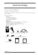
Check Your Package Thank you for purchasing the CONTEC product. The product consists of the items listed below. Check, with the following list, that your package is complete. If you discover damaged or missing items, contact your retailer. Product Configuration List - Main unit …1 AC adapter(Cable length1.5m) …1 Sheet metal for securing DC jack …1 Cross cable(Cable length1.
Copyright Copyright 2003 CONTEC CO., LTD. ALL RIGHTS RESERVED No part of this document may be copied or reproduced in any form by any means without prior written consent of CONTEC CO., LTD. CONTEC CO., LTD. makes no commitment to update or keep current the information contained in this document. The information in this document is subject to change without notice. All relevant issues have been considered in the preparation of this document.
Table of Contents Check Your Package................................................................................................................. i Copyright................................................................................................................................ ii Trademarks............................................................................................................................. ii Terminology/Abbreviations.......................................................
3. SETUP 23 Component Locations............................................................................................................ 23 Checking the Network Addresses ........................................................................................... 25 Setup .................................................................................................................................... 26 Wall Installation.................................................................................
. MEINTENANCE 61 Maintenance Tool.................................................................................................................. 61 Log File Collection................................................................................................................ 61 Using FTP to Get the Log File......................................................................................... 61 Saving the Settings File ...........................................................................
vi FX-DS540-APDL
1. Before Using the Product 1. Before Using the Product This chapter provides information you should know before using the FX-DS540-APDL. About the FX-DS540-APDL The FX-DS540-APDL is a wireless LAN Access point. It conforms to the wireless LAN standard specification IEEE802.11a/IEEE802.11b/IEEE802.11g. The FX-DS540-APDL operates in the 5 or 2.4-GHz radio frequency band.
1. Before Using the Product Outline of the FLEXLAN-DS540 series The FLEXLAN DS540 series is a wireless LAN devices adopting 5GHz band OFDM, which has t he following features. Features of the FLEXLAN-DS540 series It conforms to IEEE802.11a/b/g standard(Lisence is not needed). The FLEXLAN DS540 series corresponds to the wireless LAN standard IEEE802.11 a/b/g and you can select the wireless Lan standard for the various purpose of constructing a network. IEEE802.
1. Before Using the Product Note! This feature does not guarantee the connection of the FX-DS540-PCD to all of Wi-Fi compliant devices. Enhancements such as IP tunneling can be used with a product other than the FLEXLAN series. Multi-channel support Thirteen channels (channels 36, 40, 44, 48, 52, 56, 60, 64, 149, 153, 157, 161 and 165) for IEEE802.11a and eleven channels (channels from 1 to 11) for IEEE802.11b/IEEE802.11g can be used at the same time.
1. Before Using the Product Introduction to the FLEXLAN DS540 Series User unit (FX-DS540-PCD/PCC/PCC2) The user unit corresponds to the LAN card for a wired LAN; it is plugged into a PC for use. There is the user unit FX-DS540-PCC/PCC2 conformed to IEEE802.11a. WIREL ESS LAN CARD FX-DS540-PCC / FX-DS540-PCC2 Figure 1.1. User unit User unit (FX-DS540-PCD) There is the user unit FX-DS540-PCD conformed to IEEE802.11a/b/g. W IRELES S LAN CARD FX-DS540-PCD Figure 1.2.
1. Before Using the Product Customer Support CONTEC provides the following support services for you to use CONTEC products more efficiently and comfortably. Web Site Japanese English Chinese http://www.contec.co.jp/ http://www.contec.com/ http://www.contec.com.cn/ Latest product information CONTEC provides up-to-date information on products. CONTEC also provides product manuals and various technical documents in the PDF.
1. Before Using the Product Safety Precautions Understand the following definitions and precautions to use the product safely. Safety Information This document provides safety information using the following symbols to prevent accidents resulting in injury or death and the destruction of equipment and resources. Understand the meanings of these labels to operate the equipment safely. DANGER DANGER indicates an imminently hazardous situation which, if not avoided, will result in death or serious injury.
1. Before Using the Product Precautions Related to Electromagnetic Interference This device complies with Part 15 of the FCC Rules. Operation is subject to the following two conditions : (1) this device may not cause harmful interference, and (2) this device must accept any interference received, including interference that may cause undesired operation. This equipment complies with part 15 of the FCC rules.
1. Before Using the Product Handling Precautions DANGER Do not use the product where it is exposed to flammable or corrosive gas. Doing so may result in an explosion, fire, electric shock, or failure. CAUTION - This product contains precision electronic elements and must not be used in locations subject to physical shock or strong vibration. Otherwise, the board may malfunction, overheat, or cause a failure.
1. Before Using the Product Environment Use this product in the following environment. If used in an unauthorized environment, the board may overheat, malfunction, or cause a failure. Operating temperature 0 to 50ºC Humidity 10 to 90%RH (No condensation) Corrosive gases None Floating dust particles Not to be excessive Inspection Inspect the product periodically as follows to use it safely.
1.
2. Functions and Wireless Link Mode 2. Functions and Wireless Link Mode This chapter describes the major functions of the FLEXLAN DS540 series as a wireless LAN system and the wireless link modes of the FX-D540-APDL along with configuration examples of networks available in the wireless link modes. Roaming F unction The roaming function maintains the connection to the LAN by automatically changing the access point to which the user unit is connected when the unit moves.
2. Functions and Wireless Link Mode With the addition of an extra AP, however, the mobile station can now continue communications seamlessly. AP1 UU1 OK L W L O P (1) AP2 W L A N A N L P O W E R UU1 OK (2) AP3 W L L P O UU1 OK (3) AP : Access point (FX-DS540-APDL/APL) UU : User unit (FX-DS540-PCD/PCC/PCC2) Figure 2.2.
2. Functions and Wireless Link Mode IP Tunneling F unction (To be supported in the near future ) In TCP/IP, packets belonging to different network groups cannot normally be used. However, a technique called tunneling or IP tunnel technology can be used to temporarily modify packets belonging to different network groups so that they can be used. This technique can enable user units to communicate with the wired LAN as usual even when connected via an AP from a different network group.
2. Functions and Wireless Link Mode MAC Address Filtering MAC address filtering is the function to permit only the user units whose MAC address has been registered for an AP to log in to the AP. Using this function can reject an attempt to log in to an AP by an unidentified user unit not registered in the AP. Figure 2.4 shows a sample image of connections under control of MAC address filtering.
2. Functions and Wireless Link Mode Bridge Packet Control Bridge packet control is the function that allows an AP to pass only data from those network devices whose MAC address has been registered for the AP to its clients. Using this function can restrict communication between user units. Figure 2.5 shows a sample image of connecting under bridge packet control. The example assumes that, for bridge packet control, only the MAC address of the router is registered in AP1 and AP2.
2. Functions and Wireless Link Mode Wireless Link Mode Descriptions The AP has three wireless link modes. The available functions and network configurations differ depending on the mode. Use the wireless link mode most suitable to the type of network you are constructing. The factory default setting is simple mode. Chapters 4 and 5 describe the software setting procedures for the wireless link modes and relat ed items.
2. Functions and Wireless Link Mode Compatible Infrastructure Mode This mode allows the FX-DS540-APW to be networked with other manufacturers’ Wi-Fi certified wireless terminals other than the CONTEC’s FLEXLAN series. Communications between the wireless terminals are always made via the APs. CAUTION The Compatible Infrastructure mode does not guarantee interconnection with Wi-Fi compliant products of other manufacturers.
2. Functions and Wireless Link Mode Advanced Infrastructure Mode The Advanced Infrastructure mode is a mixture of the Standard Infrastructure and Compatible Infrastructure modes.
2. Functions and Wireless Link Mode Wireless Link Mode and Communications The table below shows which wireless terminals can communicate with each other depending on the operating mode of the AP and user unit. [Table notation and notes] 1. UU stands for “ user unit ”. 2. AP⇔UU indicates communications between a unit type AP and user unit. 3. ST indicates an “AP managed by (logged in to) another AP ” which operates in the same way as a user unit. See Chapter 5 for details of the setup procedure. Table 2.1.
2. Functions and Wireless Link Mode Comparison of Main Functions The FX-DS540-APDL has three wireless link modes. The available functions are different for each mode. The following shows a table of the relationship between the operating modes and main functions and gives a brief explanation of each function. Table 2.2.
2. Functions and Wireless Link Mode MAC address filtering This function enables connection of only the terminals whose MAC address has been registered. Bridge Packet Control This function allows the AP to pass only that data to terminals which comes from network devices having a registered MAC address. Communication between wireless terminals can be rejected when their MAC addresses are unregistered. Data encryption This function encrypts wireless data.
2.
3. Setup 3. Setup This chapter describes how to install the AP and points to note when installing. Component Locations Front Side WLAN LAN LED POWER Ground terminal Power plug Ventilation slits UTP UTP connector DIP switch Notes : Not cover the ventilation slits because of misoperation caused by overheating. Figure 3.1.
3. Setup LED indicator Three LEDs indicate the user unit connection, transmission/reception, power supply, and wired LAN connection status. Table 3.1. LED Display during Normal Operation Name State On POWER Flashing On LAN Flashing Off On WLAN Off Indicator Indicates that the device is operating. Indicates that the device is being started (going to operate after the power switch was turned on). Indicates that a wired LAN has been connected.
3. Setup Connectors Table 3.3. Connectors Item UTP 10/100M Operation / function Connects to a 10BASE-T or 100BASE-TX LAN. Ground terminal Grounds the AP via the ground terminal. Power supply 3.3VDC power supply input jack. Supply the power with this connector jack when using the bundled AC ad apter. - Power supply plug - Standard : EIAJ RC- 5320A Voltage category 2 - Polarity : Outside terminal is negative ( -) and center terminal is positive (+) - Plug diameter : 4.0mm (external diameter), 1.
3. Setup Setup Wall Installation In case of using the supported screw Refer to the main unit installation drawing to drive the screws into a wall and hang the main unit on them. (2) (1) (3) (1) Drive the screws into the wall. The dimensions are shown in the figure above. (2 locations) (2) Attach the AP case such that the two screw s on the wall insert into the wall-mount holes on the case. (3) Slide the AP unit down to hold it in place. Figure 3.2.
3. Setup Attaching Using a Magnet The magnet provided with the FX-DS540-APDL makes it easy to attach or remove the AP from metal surfaces such as steel partitions or desks. CAUTION - Do not place magnets near monitors, floppy disks, or other sensitive objects. - Moving the AP while it is mounted on a steel desk or similar surface can cause paint scratching.
3. Setup Mounting on steel desks The unit can be mounted directly on steel desks. Pull lightly to make sure that the AP does not come off easily. Select a location that gives good radio reception. The unit provides better receiver sensitivity with the internal antenna inside the top protruding above the steel surface. Antenna Figure 3.5. Mounting on Steel Desks CAUTION Do not obstruct the ventilation slits. This can cause the temperature inside the product to rise and can damage the components inside.
3. Setup Cable Installation Network Cable Installation Connect your network cable to the network connector on the AP. This model has a single 10/100BASE-TX connector. 10BASE-T or 100BASE-TX connection CAUTION - When connecting this product to a personal computer or hub use a twisted pair cable no more than 100m in length. - Use UTP cable or STP cable having category 3, 4, or 5 specifications. - When connecting with a personal computer (NIC) or hub up-link port, use a UTP cross cable (TP-X).
3. Setup Power Supply Connection This product has two methods to supply the power. Using the attached AC adapter Plug the AC adapter into a wall outlet, then connect the DC jack to the power plug in the main unit. Using the UTP cable (Optional POW-CB20, POW -CBM4 are necessary.) As the FX-DS540-APW contains a power supply separator unit, it can be powered directly from the POW -CB20 or POW -CBM4. Power supply separator unit POW-SP20 is not used.
3. Setup Ground the FX-DS540-APDL Remove the rubber plug from the ground terminal on the main unit and connect a ground wire to the terminal using the bundled external-toothed screw. Remove the rubber feet. Figure 3.8. Ground the FX-D540-APDL Securing the DC jack Using the DC jack retaining bracket as a standard accessory stops the DC jack from being removed when the DC cable is loaded to be pulled, preventiing the power from being shut off abruptly.
3. Setup Installation in a Network This section describes how to install the FX-DS540-APDL to construct a network with improved performance and discusses the general features and radio characteristics of the wireless LAN as well as the guidelines for constructing the network. Features of the Wireless Network In general, the operation of a wireless network is the same as for most other types of LAN.
3. Setup Operating Environment and Radio Waves When using this product to construct a network, install and operate it considering the radio environment to optimize the performance. Is allowed to use radio equipment at the installation location? In some medical institutions and laboratories, radio-sensitive precision instruments are used and it may be prohibited to use radio equipment. Radio waves are attenuated.
3. Setup Constructing a Network This section gives some pointers and cautions relating to constructing a network using the AP and user units, and provides some practical examples. (1) Check the coverage (cover area) of the AP. To use the AP with two or more user units logged in an infrastructure mode, all the user units must be installed within the cover area. The AP ’s coverage varies with obstacles (concrete walls, iron doors, elevator halls, etc.).
3. Setup Example 1 Use example This example constructs a network with 48 user units. Although the small area to be covered means that one AP should be enough, two APs are used to provide a backup and to ensure a reasonable level of communication speed. If AP1 or AP2 is down, the roaming feature allows user units to log in to the other AP and so provides a backup network connection.
3. Setup Example 2 Medium-sized wireless LAN L W N A N A L W O P R E eI & F T 3F PC1 Rout er 2F A L W N N A L E W O P R eIT & F Rout er 1F L W N A N A L W O P R E eI & F T PC1 W A L O P N A L N R E W & F T eI Note PC with FX-DS540-APDL/APL FX-DS540-PCD/PCC/PCC2 File S erver Figure 3.11. Medium-Sized Wi reless LAN This example constructs a wireless LAN operating over three floors of a building. A different department is located on each floor and these are separated by routers.
4. Setup Preparation 4. Setup Preparation This chapter gives an overview of how to setup the AP and describes how to access the AP settings using a web browser. Setup Methods Although the FX-D540-APDL can be set up precisely to construct an advanced wireless LAN environment, there are two different setup methods available: web browser and TELNET. The key features of each setup method are as follows. WWW browser - Provides an easy to use graphical interface.
4. Setup Preparation Setup Using a Web Browser You can setup the AP software from a PC running a web browser via the LAN or a modem. As this provides a graphical interface, setup using a web browser is much easier than using a TELNET. The factory default IP address for the AP is listed on the underside of the case.
4. Setup Preparation Connecting to the Web Browser PC When using a web browser to setup the AP, you can connect via either a LAN or a modem. Use the following procedure to connect the web browser. Connecting via a LAN (1) Connect the PC on which you will run the web browser to the same network as the AP. Alternatively, you can use a UTP cable to connect the PC directly to the AP. In that case, use a crossed-cable. The connection will not work if you use a standard straight-through cable.
4. Setup Preparation Setup Using TELNET Run Telnet on a PC connected within the same LAN to set up this product. As Telnet is a text based program, it requires a bit complicated setup operations but it can be used for setup even on an old PC with a browser which does not support setup through a web browser. Figure 4.2.
4. Setup Preparation (3) Enter the password at the [Password:] prompt. The default factory setting is no password. To login, just press the Enter key without entering anything. Figure 4.3. Password entry screen (4) When password is entered correctly, TOP menu is displayed. Figure 4.4. TOP menu CAUTION The console program uses the “Shift-JIS” character set for Kanji codes. If characters do not display correctly, check the Kanji code setting for the terminal.
4. Setup Preparation TELNET Key Operation Select items from the TELNET menus by entering the corresponding number. In addition to entering numbers, you can also use the following commands. The operation of each key is the same for all menus.
4. Setup Preparation Explanation of Top Menu and IP Settings This section describes the top menu, with the IP address and subnet mask settings as examples. Although individual menu it ems are not detailed here, they are almost the same as the settings available in the web browser. Accordingly, see Chapter 5 for details. Table 4.1. TOP Menu Menu Description 1.End Exit terminal setup. 2.Setup Select to setup AP. 3.Writing Use this command to save the settings. 4.Reboot Reboots the AP.
4. Setup Preparation Setting the IP address (1) Select [2. Setup]. Figure 4.6. IP Address Setting Screen (2) Select [3. IP Address] and enter the IP address assigned to the AP on the wired LAN. (3) Select [4. Sub-Net Mask] and enter the sub-net mask for the IP address set in step 2. (4) Select [5. Default Gateway] and enter the IP address of the default gateway. You do not need to enter an IP address if there is no default gateway. (5) Press the [W] key or return to the top menu and select [3.
5. Setup and Status Display 5. Setup and Status Display This chapter describes how to setup the AP using a web browser, explains each setting item and status display. Before you can setup the AP, perform the preparation described in “ Chapter 4 Setup Preparation”. This section describes how to perform setup using a web browser. Setup Item List Setup items are listed in the following table. The items that can be set vary with the wireless link mode.
5. Setup and Status Display Table 5.1. Setup Item List(2/3) Wireless Link Mode Setting item Standard Compatible Advanced Infrastructure mode Infrastructure mode Infrastructure mode AP Station AP Station AP fixation 802.11g 802.
5. Setup and Status Display Table 5.1.
5. Setup and Status Display Settings Basic setting Host name Assigning a name to an AP makes it easier to identify on the network. Enter a name of up to 16 alphanumeric characters. Factory default setting : (Not input) DHCP client Enabling “ DHCP client” makes the access point available as a DHCP client. Factory default setting : Disable IP address Sets the IP address of the AP. Always set the IP address.
5. Setup and Status Display IP address of the master AP When the master AP exists, specify the IP address of the AP that serves as the master AP. Factory default setting : 0.0.0.0 IP address of the backup AP When a backup AP exists, specify its IP address. Factory default setting : 0.0.0.0 Language setting Select the language displayed by the terminal or browser from “English” or “ Japanese. Factory default setting : English Password Set a password.
5. Setup and Status Display Basis Interface Disabling “ Interface” disables the internal wireless LAN module. Factory default setting : Enabled Wireless LAN standard Sets the wireless LAN standard to use. When the unit type is “ Access point”, you can select one of checkboxes. When the unit type is “ Station”, you can select more than one check boxes according to the standard of the access point to be connected.
5. Setup and Status Display Details ESSID The name of the wireless LAN to which the AP belongs. Changing the ESSID causes the AP to be disconnected from the network. Enter a name up to 32 alphanumeric characters. The name is case sensitive. Factory default setting : LocalGroup Channel number (This item available when the unit type is “Access point”.) Sets the channel number. Setting-able channel numbers are from “36” to “64”, “149” to “ 165” when IEEE802.11a and from “1” to “11” when IEEE802.11b/IEEE802.
5. Setup and Status Display 802.11g parameter This item is available when “IEEE802.11g” is selected as the wireless LAN standard. Parameter about IEEE802.11g can be set. Enabling the “802.11g Only” mode rejects access from IEEE802.11b compliant user units and accepts access only from IEEE802.11g compliant user units, resulting in communication with IEEE802.11g user units at higher data rates than both types of user units coexist with the “ 802.11g Only ” mode disabled.
5. Setup and Status Display Maximum number of logged in devices (This item available when the unit type is “ Access point”.) The number of user unit to log in AP is limited. From 1 to 254 are input. Factory default setting : 254 Roaming threshold (This item available when the unit type is “ Station”.) When the RSSI value of the currently connected access point is smaller than the setting, the unit searches for a roaming-accessible access point and roams into that access point if possible.
5. Setup and Status Display Security Encryption This setting specifies whether to enable or disable encryption. To enable encryption, select WEP or AES under “ Functions”. Specify the default transmission key no. to use when you transmit the data. Enter the key hexadecimally (uppercase and lowercase alphanumeric characters can be used). To use the WEP protocol, enter ten digits for a 64-bit key, 26 digits for a 128-bit key, or 32 digits for a 152-bit key. Enter 32 digits for a 128-bit key when AWS.
5. Setup and Status Display IEEE802.1X IEEE802.1X function Set this item to “ enable” to enable the function of IEEE802.1X. Factory default setting : Disable Re-authentication interval Specify the time interval at which to perform re-authentication, between 2 and 4320 minutes. Factory default setting : 60(minutes) RADIUS server Up to four RADIUS servers can be registered by entering their IP address, port number, and shared secret.
5. Setup and Status Display Network time Enabling the network time function can synchronize the access point time with the network time. The factory default setting is “ disable”. Before you can enable this function, you have to set the IP address and time zone of a network time server on the network. (Example: For use in Japan, enter “ +09:00” (meaning UTC + 9 hours) as the Japan standard time is nine hours ahead of Universal Time Coordinated (UTC).
5. Setup and Status Display Trap destination IP address Trap is the function to notify a user of a change made within the SNMP agent system. The trap function can be enabled by specify the IP address of the destination user. The SNMP manager having the IP address specified here can manage trap information about the AP. If the network contains more than one AP, it is advisable to register the same IP address so that all the APs can be managed on one machine. Up to three destination IPs can be registered.
5. Setup and Status Display Log function The FX-DS540-APDL can preserve log information. See Chapter 6 for details of the logged data and data collection methods. Log function This specifies whether or not to enable logging. The collected log data (2048 at Max.) is stored in internal memory. Factory default setting : Disable Overwrite setting This specifies whether or not to overwrite old data when the number of log entries reaches the maximum.
5. Setup and Status Display Status display A list of status information on this product can be displayed by selecting “ Status” after logging in through a web browser or Telnet. This displays the following information. Configuration data This includes the firmware version, IP address. Interface information The browser displays information about the Ethernet, wireless LAN, and series interfaces.
5.
6. Meintenance 6. Meintenance This chapter describes how to perform maintenance on the AP and explains the tools to be used. Here, “maintenance” means the following: log file collection, firmware upgrades, and saving and restoring the software settings. Maintenance Tool This maintenance tool is available for the FTP. This section describes how to use the tool. Log File Collection The AP collects the following log data. To collect the log file, you collect it by using FTP via the LAN.
6. Meintenance Saving the Settings File Making a backup of the AP software settings file has the following benefits: - If you have more than one AP and all APs have the same settings, you just need to setup one AP then use the resulting settings file for the other APs. (However, as this sets the same IP address for all APs, you need to change the IP address separately.) - The old settings can be restored easily if a fault causes the settings file to be erased.
6. Meintenance Restoring the Software Settings Using this function has the following benefits: - If you have more than one AP and all APs have the same settings, you just need to setup one AP then use the resulting settings file for the other APs. (However, as this sets the same IP address for all APs, you need to change the IP address separately.) - The old settings can be restored easily if a fault causes the settings file to be erased.
6. Meintenance Upgrading the Firmware The AP firmware may be upgraded to resolve any bugs found in the software or to add new functions. Contact CONTEC via our web site for details of the latest firmware. The firmware is stored the AP memory with the following file name. File name : apfirm.bin Performing an Upgrade Using FTP (1) Run FTP to log in to the AP. (2) Change the transfer mode to binary. (3) Transfer the firmware file. (4) Issue the reset request command (quote crst). (5) Quit FTP.
7. Troubleshooting 7. Troubleshooting This chapter describes common problems that may occur with this product and what to do about them. If any problems occur that are not described here, check to confirm that the re-occur, then contact the store where you purchased the product. When Communication Fails Check hardware - If connecting via the wired LAN, check that the LAN cable is connected correctly. - Check that there are no obstructions in the way of this product.
7. Troubleshooting Check the peripheral environment and place of installation - A nearby source of electromagnetic interference can prevent communicat ion. In general locations (excluding factories) the following may be sources of electromagnetic emissions. - 5GHz band not conforming to IEEE802.11(when using by IEEE802.11a) or 2.4GHz band(when using by IEEE802.11b/IEEE802.11g) wireless network. - Electric devices which give off 2.
8. Appecdix 8. Appecdix Factory Default Settings List Hardware Setup - FX-DS540-APDL switch1 : OFF switch 2 : OFF ON 1 2 Figure 8.1. DIP Switch Initial setup Table 8.1. Initial setup list (1/4) Setting item Setting contents(First default) Host name ( Enter a string of up to 16 single-byte (Blank) alphanumeric characters.) DHCP client Disable / Enable IP address (When disabled setting of DHCP client sets : Seal on the back of housing enable) Subnet mask 255.0.0.
8. Appecdix Table 8.1. Initial setup list (2/4) Setting item Setting contents(First default) Interface Enable, Disable Wireless LAN standard IEEE802.11a, IEEE802.11b, IEEE802.11g Wireless connection mode Standard, Compatible, advanced infrastructure Unit type Access point, Station *In compatible mode, you can not select station. ESSID (single-byte alphanumeric characters can be up LocalGroup to 32 characters long and .the password is case sensitive.
8. Appecdix Table 8.1. Initial setup list (3/4) Setting item Setting contents(First default) 11g 802.
8. Appecdix Table 8.1. Initial setup list (4/4) Setting item Setting contents(First default) < Extensions > Bridge Packet Control (MAX 32 entries) Disable, Enable [List edit : MAX 32 entires] Network time, function Disable, Enabled Network time, IP address (IP address of network time server) Network time, time zone +09:00 ( Japanese time zone is between +09:00.
8. Appecdix Setup / Status Items list WWW brouser Setting |− Basic setting |− Ethernet |− Wireless LAN |− Basis |− Details |_ Security |− IEEE802.
8. Appecdix Terminal Fxit Setting |− Host name |− DHCP client |− IP address |− Subnet mask |− Default gateway |− Access point construction |− Access point type |− IP address of the masuter AP |− IP address of the backup AP |− Ethernet | |− Port speed | |_ Link down sense |− Wireless | |− Interface | |− Wireless LAN standard | |− Wireless connection mode | |− Unit type | |− Access point type | |− IP address of the masuter AP | |− IP address of the backup AP | |− ESSDI | |−Channel No.
8.
8. Appecdix Product Specifications Physical Specifications Table 8.2. Product Specifications Specification Wired LAN unit Wireless LAN unit FX-DS540-APDL Ethernet standard Data transmission speed IEEE802.3(10BASE-T) IEEE802.3u(100BASE-TX) 10/100Mbps Access method CSMA/CD Communication type Half Duplex, Full Duplex Number of ports 1(10BASE-T/100BASE-TX) IEEE802.11a IEEE802.11b IEEE802.11g Transmission format IEEE802.
8. Appecdix Software Specifications Table 8.3. Software Specifications Specification Protocols FX-DS540-APDL IP(RFC791) , ICMP(RFC792) , UDP(RFC768) , TCP(RFC793,896), ARP(RFC826) , HTTPD(RFC1866), TELNET(RFC), FTPD(RFC959), TFTP(RFC783,906), DHCP(RFC2131) Environmental Specifications for Installing the FX-DS540-APDL Table 8.4. Environmental Specifications (Environmental Specs) Specification FX-DS540-APDL DC supply voltage(Input) 3.3VDC±5% 1.3A(Max.
8. Appecdix External Dimensions 175 81 W LAN LAN 26.5 POW ER U TP Figure 8.2.
8. Appecdix LEDs Front WLAN WL AN LA N LED LAN POW ER POWER Figure 8.3. FX-DS540-APDL(Front) During Normal Operation Table 8.6. During Normal Operation Name Status POWER LAN Indicator ON Indicates that the device is operating. Flashing Indicates that the device is being started (going to operate after the power switch was turned on) ON Indicates that a wired LAN has been connected. Flashing Indicates the transmitting / receiving between terminal connected by the wired LAN and the data.
8. Appecdix Others Table 8.7. When Writing Firmware Name Status POWER Flashing LAN simultaneously Indicator Writing firmware is in progress WLAN Table 8.8. Error Display(The POWER LED blinks twice) Name Status LAN Flashing Wired LAN error WLAN Flashing Wireless LAN error Indicator Input/Output Interface Pin Assignment for UTP Port Table 8.9. UTP Port Pin Assignments Pin.
8. Appecdix Comparison to FLEXLAN DS110 series terminology The table below compares terms used for the FLEXLAN DS540 series and those for the FLEXLAN DS110 series. Table 8.10.
8. Appecdix Glossary SQE(Signal Quality Error) (Heartbeat) This uses the same signal line as the collision signal for the purpose of notifying the transmitting terminal that the packets sent from the terminal are sent correctly over the cable. PPP(Point to Point Protocol) A protocol for communicating using TCP/IP over a serial line.
8. Appecdix Brouter A router with an added bridge function. When data received from one network cannot be processed by the router because a different protocol is used, the bridge function can be used to send the data on to the other network. LAN(Local Area Network) A network configured from mutual connections between computers within a limited area. Also called an "intranet" or "business or regional data communications network.
8. Appecdix Peer-To-Peer A network in which two or more nodes can communicate directly with each other without going through another device. AP(ACCESS POINT) Access point. In the FLEXLAN DS540 series, the access point serves as a bridge between a wired network and a wireless network and provides IP tunneling; it is indispensable for the versatility and scalability of the wireless network. User Unit In FLEXLAN DS540 series, user unit means the device loading FX-DS540-PCC/FX-DS540-PCC2/FX-DS540-PCD.
Atheros, ABG and Total 802.11 are trademarks of Atheros Communications, Inc. CONTEC CO.,LTD is using the Atheros trademarks with permission from and on behalf of Atheros Communications, Inc. FX-DS540-APDL User’s Manual CONTEC CO., LTD. December 2003 Edition 3-9-31, Himesato, Nishiyodogawa-ku, Osaka 555-0025, Japan Japanese http://www.contec.co.jp/ English http://www.contec.com/ Chinese http://www.contec.com.