SBC Series Single Board Computer Full Size PICMG with LANx2, VGA, Audio SPI-8451-LLVA SPI-8452-LLVA with LAN, VGA, Audio SPI-8451-LVA User’s Manual CONTEC CO.,LTD.
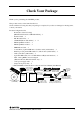
Check Your Package Thank you for purchasing the CONTEC product. The product consists of the items listed below. Check, with the following list, that your package is complete. If you discover damaged or missing items, contact your retailer.
Copyright Copyright 2007 CONTEC CO., LTD. ALL RIGHTS RESERVED. No part of this document may be copied or reproduced in any form by any means without prior written consent of CONTEC CO., LTD. CONTEC CO., LTD. makes been considered in the preparation of this document. Should you notice an omission or any questionable item in this document, please feel free to notify CONTEC CO. LTD. All relevant issues have been considered in the preparation of this document.
Table of Contents Check Your Package ................................................................................................................................ i Copyright .................................................................................................................................................ii Trademarks ..............................................................................................................................................ii Caution about Battery.........
RS-422 / RS-485 specifications.............................................................................................................24 IDE RAID Connector: CN14, CN8 (SPI-8451-LLVA only)................................................................25 Audio Connector: CN9 ..........................................................................................................................26 CD-IN Connector: JCDIN ....................................................................................
Deleting an array ............................................................................................................................ 50 Rebuilding a mirrored Array .......................................................................................................... 51 Viewing Controller Settings........................................................................................................... 52 Installing the drivers Windows 2000/XP ...................................................
vi SPI-8451-LLVA, SPI-8452-LLVA, SPI-8451-LVA
1. Introduction 1. Introduction This product is a full-size PICMG single-board computer that uses the Intel(R) 845GV chipset and can mount a 1.7G - 2.8GHz (FSB400/533MHz) Intel(R) Pentium(R) 4 processor. The board supports a maximum of 2GB DDR SDRAM and features an all-in-one design that incorporates a range of different interfaces. The SPI-8451-LLVA supports Dual View with two LAN ports (one of which provides GigaBit support) and an LVDS interface.
1. Introduction Option List CPU PCP4-28S Pentium 4 2.8GHz CPU with HeatSink-FAN *1 PCP4-28 Pentium 4 2.8 GHz CPU with HeatSink-FAN *2 PCP4-24 Pentium 4 2.4GHz CPU with HeatSink-FAN *2 PCP4C-20S Celeron 2.0GHz CPU with HeatSink-FAN *1 PCP4C-20 Celeron 2.0GHz CPU with HeatSink-FAN *2 *1 This board requires the width for 2 slots (except CPU heatsink-fan hight). Furthermore, since a heatsink-fan *2 This board requires the width for 2 slots (except CPU heatsink-fan hight).
1. Introduction Customer Support CONTEC provides the following support services for you to use CONTC products more efficiently and comfortably. Web Site Japanese http://www.contec.co.jp/ English http://www.contec.com/ Chinese http://www.contec.com.cn/ Latest product information CONTEC provides up-to-date information on products. CONTEC also provides product manuals and various technical documents in the PDF.
1. Introduction Safety Information This document provides safety information using the following symbols to prevent accidents resulting in injury or death and the destruction of equipment and resources. Understand the meanings of these labels to operate the equipment safely. DANGER DANGER indicates an imminently hazardous situation which, if not avoided, will result in death or serious injury.
1. Introduction Environments Use this product in the following environment. If used in an unauthorized environment, the board may overeat, malfunction, or cause a failure. Operating temperature 0 - 60oC Operating humidity 10 - 90%RH (No condensation) Corrosive gases None Floating dust particles Not to be excessive Inspection Inspection the product periodically as follows to use it safely. - Check that the board has no dust or foreign matter adhering.
1.
2. System Reference 2. System Reference Specification Table 2.1. Functional Specifications [SPI-8451-LLVA, SPI-8452-LLVA] < 1 / 2 > Specifications Type SPI-8451-LLVA SPI-8452-LLVA CPU(Option) Intel(R) Pentium(R) 4 Processor 1.7G - 2.8GHz (FSB400/533MHz) Intel(R) Celeron(R) Processor 1.7G - 2.6GHz (FSB 400 MHz) (Only corresponding to the Northwood core) Intel(R) Celeron(R) D Processor 2.26G - 2.
2. System Reference Table 2.1. Functional Specifications [SPI-8451-LLVA, SPI-8452-LLVA] < 2 / 2 > Specifications Type RTC/CMOS SPI-8451-LLVA SPI-8452-LLVA The RTC (real-time clock) and CMOS data backup by the lithium battery. The Lithium battery specification is shown in table Specification BR-2/3AC2P Voltage 3V Capacity 1200mAh Weigh 15.5g * Backup time: Over 10 years at none AC power 25ºC. * Real Time Clock accurate: ±3 minutes/month at 25ºC.
2. System Reference Table 2.2. Functional Specifications[SPI-8451-LVA] < 1 / 2 > Type Specifications CPU(Option) Intel(R) Pentium(R) 4 Processor 1.7G - 2.8GHz (FSB400/533MHz) Intel(R) Celeron(R) Processor 1.7G - 2.6GHz (FSB 400 MHz) (Only corresponding to the Northwood core) Intel(R) Celeron(R) D Processor 2.26G - 2.8GHz (FSB 533MHz) Cache Built in CPU Processor socket Socket 478 Memory (Option) Two DIMM 184 pin socket for PC2700 DDR SDRAM up to 2GB.
2. System Reference Table 2.2. Functional Specifications [SPI-8451-LVA] < 2 / 2 > Type Specifications Power Management Power management setup via BIOS Modem Ring On/Wake One LAN Supports PC98/PC99 ACPI Power management Bus specification/Size (mm) PCI/ISA (PICMG) *1 / 338 (L) x 122 (H) x 28(W) *2 DC Power Requirements +5VDC±5% +12VDC±5% +5VSB (Stand by) ±5% (only when using the ATX power supply) Operating temperature / Operating Humidity Intel Pentium 4 Processor 2.8 GHz : +5VDC, 5.4A +12VDC, 7.
2. System Reference Power Requirements Your system requires a clean, steady power source for reliable performance of the high frequency CPU on the product, the quality of the power supply is even more important. Power Consumption For typical configurations, the CPU board is designed to operate with at least a 250W power supply. A higher-wattage power supply should be used for heavily-loaded configurations.
2. System Reference Connector & Jumper Location DIMM2 DIMM1 CN3 CN5 CN1 JP1 JP2 JP3 JIR1 JCDIN1 CN2 CN9 PW1 CN10 CN24 CN15 CN4 CN14 CN8 CN6: COM1 CN11 CN12 CN13 CN7: COM2 CN16 CN21 BATT1 CN17 CN22 JKB1 JKB2 FAN2 CN18 CN19 CN20 JBAT1 FAN1 CN23 JKB3 JKB4 Figure 2.1.
2. System Reference Block Diagram SOCKET 478 P4/Celeron D PROCESSOR Processor PWM CLOCK ICS950201 DATA CTRL ADDR AGTL+BUS DATA CTRL ADDR RGB BUS DVI Connector (SPI-8451-LLVA, SPI-8452-LLVA only) TMDS SiI164 GMCH DDRS DRAM BROOKDALE-GV FCBGA760 DVOS BUS IDE Connect USB 2.
2.
3. Hardware Installations 3. Hardware Installations This chapter provides information on how to use the jumpers and connectors on this product in order to set up a workable system. Installation procedure (1) Confirm the power supply is off. (2) Install the processor with correct orientation. (3) Insert the DRAM module with correct orientation. (4) Mount the fan on the top of the processor and connect it to FAN1 connector. (5) Insert +12V Power Supply cable to PW1 connector.
3. Hardware Installations CPU Installation: This product supports a single Intel 478pin FC-PGA2 type Pentium 4, Celeron D or Celeron processor. The processor’s VID pins automatically program the voltage regulator on the CPU board to the required processor voltage. The host bus speed is automatically selected. The processor connects to the CPU board through the 478-pins socket. The CPU board supports the processors listed in table below: Table 3.1.
3. Hardware Installations Main Memory Installation: DIMM1, DIMM2 This product’s PICMG Industrial CPU Board supports one single-side or double-sided DDR200 (PC1600)/266(PC2100)/333(PC2700) unregistered DIMM, 184-pin DIMM sockets for a maximum memory of 2GB. Using the non-ECC DDR SDRAM DIMM.
3. Hardware Installations ATX Power Control Connector: CN1 When used with an ATX-compliant power supply that supports remote power on/off, the CPU board can turn off the system power through software control. To enable soft-off control in software, advanced power management must be enabled in the Setup program and in the operation system. When the system BIOS receives the correct APM command from the operating system, the BIOS turns off power to the computer. Table 3.3.
3. Hardware Installations Front Panel Connector: CN2 This header can be connected to a front panel power switch. The front panel connector includes headers for these I/O connections: Power switch This header can be connected the power on switch when ATX power supply use. Power LED This header can be connected to an LED that will light when the computer is powered on.
3. Hardware Installations Floppy Disk Connector: CN3 The floppy interface can be configured for the following floppy drive capacities and sizes: - 360 KB, 5.25-inch - 1.2 MB, 5.25-inch - 720 KB, 3.5-inch - 1.44 MB, 3.5-inch - 2.88 MB, 3.5-inch This connector supports the provided floppy drive ribbon cable. After connecting the single and to the board, connect the two plugs on the other end to the floppy drives. Table 3.5. 33 Floppy Disk Drive Connector CN3 1 34 20 2 Pin No.
3. Hardware Installations Primary / Secondary IDE Connector: CN13/CN4 This product provides two bus-mastering PCI IDE interface. This interface support PIO Mode 3, PIO Mode 4, ATAPI devices (e.g., CD-ROM), and Ultra DMA/33/66/100 synchronous-DMA mode transfers. The BIOS supports logical block addressing (LBA) and extended cylinder head sector (ECHS) translation modes. The BIOS automatically detects the IDE device transfer rate and translation mode.
3. Hardware Installations Parallel Port Connector: CN5 The parallel port bracket can used to add an additional parallel port for additional parallel devices. There are four options for parallel port operation: - Compatible (Standard mode) - Bi-Directional (PS/2 compatible) - Bi-Directional EPP. A driver from the peripheral manufacturer is required for operation. - Bi-Directional High-speed ECP Table 3.7. Parallel Port Connector CN5 25 1 26 2 Pin No. Function Pin No.
3. Hardware Installations Serial Port connector: CN6, CN7 Serial1 (CN6) and Serial2 (CN7) are 10-pins box-headers. Both are on board serial ports of the product. The following table shows the pin assignments of these connectors. RS-232C/422/485 assigned for Serial2 (CN7) connector only. Table 3.8. Serial Port connector Pin No. RS-232C RS-422* 1 DCD TX- TX- 2 RXD TX+ TX+ 3 TSD RX+ RX+ 4 DTR RX- RX- 5 GND GND GND 6 DST RTS- N.C. 7 RTS RTS+ N.C. 8 CTS CTS+ N.C.
3. Hardware Installations RS-422 / RS-485 specifications - Transmission system: Asynchronous, half-/full-duplex serial transmission conforming to RS-422/RS-485 - Baud rate: 50 - 115,200bps (programmable) - Signal extensible distance: 1.2km Max. RTS# JP3: 7-8 47k Ω RXD 6.2kΩ R JP3: 4-6 6.2kΩ 47k Ω JP3: 5-6 TXD 10 5 120 Ω JP2: 5-6 120 Ω JP2: 7-8 D +5V CTS# CN7 Terminating Resister 6 1 47k Ω 6.2kΩ R 120 Ω JP2: 1-2 6.2kΩ 47k Ω RTS# Figure 3.1.
3. Hardware Installations IDE RAID Connector: CN14, CN8 (SPI-8451-LLVA only) The CPU board SPI-8451-LLVA using the chipset of Promise PDC20265R for IDE RAID port that with the bus-mastering design takes full advantage of multi-tasking, multi-threading operating systems and greatly improves performance. Provides scatter/gather DMA mechanism that complies with Revision 1.0 of the programming interface for Bus Master IDE Controller.
3. Hardware Installations Audio Connector: CN9 This connector connects the Audio jack cable. Table 3.11. CN9 10 9 2 1 Audio Connector Pin No. Function Pin No. Function 1 LINE-OUT-R 2 LINE-OUT-L 3 GND 4 N.C. 5 N.C. 6 MIC-IN 7 GND 8 GND 9 LINE-IN-R 10 LINE-IN-L CD-IN Connector: JCDIN This connector is used to connect CD Audio cable from CD-ROM or DVD drive to onboard sound. Table 3.12. JCDIN 1 26 4 CD-IN Connector Pin No.
3. Hardware Installations DVI-I Connector: CN15 (SPI-8451-LLVA, SPI-8452-LLVA only) This connector is DVI-I connector for CRT/LCD. The pin assignment is shown below. In use the CRT (Analog RGB display), need the DVI-I-Analog RGB conversion adapter. 20 pin and 21 pin are connecting to Serial1 for the touch panel signal. CN6 cannot be used when using this signal. Table 3.13. DVI-Analog RGB converter Connector-type DVI-I 29pin 1 C1 8 C2 C5 9 Pin No. Signal name 17 Pin No.
3. Hardware Installations VGA Connector: CN24 (SPI-8451-LVA only) It is a VGA CRT connector. The pin assignments are as follows: Table 3.14. VGA Connector (CN24) 5 10 15 28 1 6 11 PIN No. Function PIN No. Function 1 Red 2 Green 3 Blue 4 N.C 5 GND 6 GND 7 GND 8 GND 9 VCC 10 GND 11 N.C 12 DDC data 13 H-Sync 14 V-Sync 15 DDC clock 16 N.
3. Hardware Installations LVDS LCD panel Connector: CN11 / CN12 (SPI-8451-LLVA, SPI-8452-LLVA only) CN11 and CN12 consist of 20-pin connectors that using the Hirose’s DF13A-20DP-1.25V. This product supports LVDS LCD panel display. LVDS 18bit output, VGA (640×480), SVGA (800 x 600), XGA (1024 x 768), SXGA (1280 x 1024) Please ask us the connectable display. Table 3.15. 20 LVDS LCD panel Connector CN11 19 20 19 Pin No. Function Pin No.
3. Hardware Installations LCD Backlight Connector: CN10 (SPI-8451-LLVA, SPI-8452-LLVA only) This is a 5-pin connector for backlight connector. Table 3.16. LCD Backlight Connector CN10 1 2 3 4 5 Pin No. Function 1 Backlight 2 GND 3 N.C. 4 GND 5 VCC Housing: PHR-5 (JST) Contact: SPH-002T-P0.5S (JST) Backlight : +12V Backlight power out (1A Max.) VCC : +5V power out (500mA Max.
3. Hardware Installations GIGA LAN Connector: CN16 (SPI-8451-LLVA, SPI-8452-LLVA only) This connector is for the 10/100/1000 Base-TX LAN I/F that has LED indicated the Transfer rate / Link / Act status of Ethernet capability of the CPU board. The follow table shows the pin assignments of this connector. Table 3.17. GIGA LAN connector (CN16) Speed LED 8 CN16 Link / ACT LED 1 Pin No. Function Pin No.
3. Hardware Installations USB Connector: CN18, CN19, CN20 This product have three USB (v2.0 compliant) pin-header connector (USB0/1: CN18, USB2/3: CN19, USB4/5: CN20). Table 3.19. USB Pin-header Connector (CN18, CN19, CN20) CN18/19/20 9 1 10 2 Pin No. Function Pin No. 1 VCC0 2 VCC1 3 USBP0- 4 USBP1- 5 USBP0+ 6 USBP1+ 7 USBG 8 USBG 9 N.C. 10 GND Function * Pin 9 is reverse-of the connector and empty pin of prevention.
3. Hardware Installations Keyboard / Mouse Connector: CN22 The CPU board provides a standard PS/2 keyboard/mouse connector for attaching a PS/2 keyboard/mouse. You will connect with an add-on cable for a PS/2 keyboard/mouse. You can select that plug a PS/2 mouse directly, PS/2 keyboard directly or both (use Y-cable) by jumper setting. The PS2 Connector pin definition is shown below: Table 3.21. Keyboard / Mouse Connector (CN22) Pin No.
3. Hardware Installations +12V Power supply Connector: PW1 The power supply that conformed for ATX12V is used, this connector connect 4Pin +12V cable directly from power supply. Use the +12V power cable of the accessories, when other power supplies are used. Table 3.24. PW1 4 3 2 1 +12V power supply Connector Pin No. Function Pin No. Function 2 GND 4 +12V 1 GND 3 +12V CPU FAN Connector: FAN1 FAN1 is a 3-pins box-header for the CPU cooling fan power connector. The fan must be a 12V fan.
4. Jumper Setting 4. Jumper Setting RS-232/422/485 Selector: JP1, JP3 Table 4.1. RS-232C/422/485 Selector (JP1, JP3) RS-232C (Default) RS-422 RS-485 JP1 23 21 19 17 15 13 11 9 7 5 3 1 9 JP3 7 5 3 1 25 22 20 18 16 14 12 1 0 8 6 4 2 10 8 6 4 2 JP1 23 21 19 17 15 13 11 9 7 5 3 1 9 25 22 20 18 16 14 12 1 0 8 6 4 2 10 8 6 4 2 JP1 23 21 19 17 15 13 11 9 7 5 3 1 9 25 22 20 18 16 14 12 1 0 8 6 4 2 10 8 6 4 2 JP3 7 5 3 1 JP3 7 5 3 1 1.
4. Jumper Setting RS-422 Setting RTS# SERIAL2 JP3: 7-8 TXD# D 120Ω JP3: 7-8 JP3: 4-6 R RXD# 120Ω JP2: 5-6 JP3: 5-6 RTS TXRTSTX+ RTS+ RX+ CTS+ RXCTS- 6 7 8 9 1 2 3 4 5 D 120Ω JP2: 3-4 CTS R 120Ω JP2: 1-2 Figure 4.1.
4. Jumper Setting RS-485 Setting RTS# SERIAL2 JP8: 7-8 TXD# 6 D 7 120 Ω JP7: 7-8 8 JP8: 4-6 JP8: 5-6 Figure 4.2. RXD# 9 R 120 Ω JP7: 5-6 1 DATA- 2 3 DATA+ 4 5 RS-485 Setting I/O addresses and instructions The table below lists I/O addresses for use as SERIAL2. Table 4.2.
4. Jumper Setting RS-422/485 Terminator: JP2 Table 4.3.
5. Board Resources 5. Board Resources System address map The GMCH memory map includes a number of programmable ranges. All of these ranges must be unique and non-overlapping. There are no hardware interlocks to prevent problems in the case of overlapping ranges. Accesses to overlapped ranges may produce indeterminate results. Table 5.1. Compatibility Area Address 0 - 640KB 640 - 768KB 768 - 896KB 896 - 960KB 960 - 1MB Table 5.2.
5. Board Resources PCI Routing Information Tabled 5.3.
6. RAID Controller 6. RAID Controller Important data protection information You should back up all data before installing any drive controller or storage peripheral. We are not responsible for any loss of data resulting from the use, disuse or misuse of the RAID device. CAUTION When you need to use RAID function, you mast connect compatible IDE device with connector CN8 and CN14. DANGER - Before installing the driver into an existing existing system, backup any necessary data.
6. RAID Controller 3. Install the hard drives into the hard drive bays of your system, including the power cables. 4. Attach one Ultra ATA cable to each hard drive. Then attach one cable to each of the IDE connector on the SPI-8451-LLVA board. The colored edge of the cable(s) indicates pin 1, and the blue cable connector must be attached to the SPI-8451-LLVA connector.
6. RAID Controller Creating Your Disk Array You will now use the FastBuild™ BIOS utility to create your array using the attached drives. There are three different scenarios in creating this array. You can create an array for performance, you can create a Security array using new hard drives (recommended), or you can create a Security array using an existing hard drive and a new hard drive. DANGER If creating a Security array using an existing hard drive, backup any necessary data.
6. RAID Controller Creating an Array for Performance CAUTION RAID controller allows users to create striped arrays with 1, 2 drives. To create an array for best performance, follow these steps: 1. Using the Spacebar, choose “Performance” under the Optimize Array for section. 2. Select how you will use your PC most under the Typical Application to use section. are A/V Editing, SERVER, and DESKTOP (the default). 3. Press keys to Save and create the array. 4. Reboot your system. 5.
6. RAID Controller Creating a Security Array with An Existing Data Drive CAUTION RAID controller permit only two drives to be used for a single Mirrored array in Auto Setup. You would use this method if you wish to use a drive that already contains data and / or is the bootable system drive in your system. You will need another drive of identical or larger storage capacity. Follow these steps: 1. Using the Spacebar, choose “Security” under the Optimize Array for section. 2. 3.
6. RAID Controller Using FastBuild™ Configuration Utility The FastBuild™ Configuration Utility offers several menu choice to create an manage the drive array on the RAID controller. For purposes of this manual, it is assumed you have already created an array in the previous chapter and now wish to make a change to the array or view other options.
6. RAID Controller Using the Main Menu This is the first option screen when entering the FastBuild™ Setup. FastBuild (tm) Utility 1.xx (c) 1996-2001 Promise Technology, Inc. [ Main Menu ] Auto Setup……………………………………………….. [ 1 ] View Drive Assignments …………………………………[ 2 ] View Array………………………………………………. [ 3 ] Delete Array………………………………………………[ 4 ] Rebuild Array……………………………………………..[ 5 ] Controller Configuration………………………………….[ 6 ] [ Keys Available ] Press 1..6 to Select Option [ESC] Exit 1.
6. RAID Controller Creating Arrays Automatically The auto Setup <1> selection from the Main Menu can intuitively help create your disk array. It will assign all available drives appropriate for the disk array you are creating. After making all selections, use Ctrl-Y to save selections. FastBuild™ will automatically build the array. FastBuild (tm) Utility 1.xx © 1996-2001 Promise Technology, Inc.
6. RAID Controller Viewing Drive Assignments The View Drive Assignments <2> option in the Main Menu displays whether drives are assigned to a disk arrays or are unassigned. Under the “Assignment” column, drives are labeled with their assigned disk array or shown as “Free” if unassigned. Such “Free” drives can be used for a future array or used as a spare drive when a drive fails in a mirrored array. Unassigned drives are not accessible by the OS.
6. RAID Controller Deleting an array The Delete Array <4> Menu option allows for deletion of disk array assignments. This is not the same as deleting data from the drives themselves. If you delete an array by accident (and before it has been used again), the array can normally be recovered by defining the array identically as the deleted array. DANGER Deleting an existing disk array could result in its data loss.
6. RAID Controller Rebuilding a mirrored Array Rebuild Array <5> Menu option is necessary to recover from an error in a mirrored disk array. You will receive an error message when booting your system from the FastTrak BIOS. CAUTION Drives MUST be replaced if they contain any physical errors. Follow these steps BEFORE using the Rebuild Array menu option: 1. On boot up, the FasTrak100-Lite Startup BIOS will display an error message identifying which drive has failed. 2.
6. RAID Controller 12. Press [Enter] and confirm that the data will be copied on to the selected drive. All data on the replacement drive will be written over with mirrored information from the array drive. A progress bar will appear as below. Please Wait While Duplicating The Image 10% Complete 13. Once the rebuild process is complete, the user will be asked to reboot the system.
6. RAID Controller Installing the drivers Windows 2000/XP Installing Driver During New windows 2000/XP Installation CAUTION Before the Windows 2000/XP installing, please copy the whole files and folder in the folder as follows “RAID\Win2000\” (“RAID\Winxp\”) of the Driver CD-ROM to a floppy disk. 1. Floppy Install: Boot the computer with the Windows 2000 installation diskettes. 2. Floppyless Install: Boot from floppy and type “WINNT”. After files have been copied, the system will reboot.
6. RAID Controller Installing Driver in Existing windows 2000/XP System WARNING If you will be moving the boot drive containing the existing Windows 2000/XP operating system to a mirrored RAID 1 array on the controller, the controller driver MUST be loaded to the hard drive while it is still attached to your existing hard drive controller. Do not attach this drive or any other hard drive to the controller before completing this step.
6. RAID Controller Using the FastCheck Monitoring Utility You can monitor the operating status of all arrays and drives configured on the RAID controller using the supplied FastCheck monitoring utility for Windows-based operating system (Windows 2000 / XP). FastCheck generates visual and audible messages alerting you of possible problems with the disk array or controller.
6. RAID Controller Closing FastCheck Once FastCheck is opened (either automatically on startup or manually), the monitoring utility remains running in the background even if go user “closes” the FastCheck windows. To completely shut down FastCheck icon on the Taskbar. 1. Right-click the FastCheck icon on the Taskbar. 2. Select Exit from the pop-up window. 3. FastCheck™ no longer be running and will no longer be monitoring the array.
6. RAID Controller Using FastCheck Array Windows Once FastCheck is selected, the FastCheck Monitoring Utility window will appear. The main pane has three information window tabs: Array, Controller, and Options. The user can switch screens by clicking on the tab. The Array window is the active screen by default as shown below: The Array Window (see above) displays information about the arrays configured on your FastTrak100-Lite through the FastBuild BIOS.
6. RAID Controller Viewing Arrayed Drive Information By left-clicking on a drive member of an array in the left pane, the right pane shows the following information categories for that drive: Status: (also shown under the Array Window) can be Functional, Critical, or Offline. The meanings are shown below. Functional: Means the drive is working normally. Critical: A problem has been detected in the drive and the drive taken offline as part of a mirroring array.
6. RAID Controller Using Array Pull-down Menu At the bottom of the Array window, it indicates to right-click on an Array to perform synchronization or rebuild operations. Right-clicking displays the following pull-down menu: From this menu, users may choose to have the window Always Appear on Top of applications, Minimize, Synchronize mirrored drives, Rebuild a mirrored array, use About to check FastCheck version#, or Exit the on screen window.
6. RAID Controller To synchronize, choose the Array Tab View. Right-click on the array you wish to synchronize and choose “Synchronize” from the context menu. Click “Yes” to initiate Synchronization (see below) when the Confirmation window appears. To cancel this option, click the NO button. WARNING Once initiated, synchronization can NOT be halted in order to prevent data errors. Once Synchronization is confirmed, the following information screen appears. Click OK button or close the window to proceed.
6. RAID Controller Rebuilding An Array This command effectively copies or overwrites data from an existing data drive in the array on to a blank drive. The operation will be typically used when a failed drive has been replaced with a new drive as part of a mirrored array. To perform a Rebuild, choose the Array Tab View. Right click the array number and choose Rebuild from the context menu. Once Rebuild is selected, you will be asked to “Initialize Rebuild process on Array #” by clicking OK.
6. RAID Controller Click the Next button to proceed to Rebuild Wizard Step 2 or Cancel button to stop. Rebuild Wizard Step 2 confirms the Target or “Rebuild” disk by Array # and drive ID. Click Finish button to initiate physical Rebuild, Back button to review Step 2, or Cancel button to Stop. A final confirmation window appears as below: Click “Yes” to initiate Rebuild. To cancel this option, click the No button. WARNING Once initiated, Array Rebuild can NOT be halted in order to prevent data errors.
6. RAID Controller Using Controller Windows Clicking on the Controller tab, will reveal the Controller Window. This displays physical information about the location of FastTrak100-Lite, data channels on the card, and the attached drives.
6. RAID Controller Viewing IDE Channel Information Left-clicking on a given Channel icon or # in the left pane, will show the Base IO addresses of the channel in the right pane (used for troubleshooting). Viewing Drive Information Left-clicking on a given Drive icon or ID in the left pane, will show similar information categories as the Array Window Drive Information in the right pane. Status (also shown under the Array Window) can be Functional, Critical, or Offline. are shown below.
6. RAID Controller S.M.A.R.T. Status: Indicates whether attached hard drive implements Self-Monitoring Analysis & Reporting Technology to predict drive failure Size: Indicates capacity of individual drive Location: Shows physical location of drive. Indicates on which IDE channel (1 or 2), and whether drive is Master or Slave on cable. This allows user to identify drives for removal/replacement.
6. RAID Controller Selecting Notification Options This section of the Options windows allows users to select how they are notified of a system event. A System Event includes driver-initiated Rebuilds (automatic rebuild using a “hot” spare standby drive), user-initiated manual Rebuilds or manual Synchronization, and Error-Handling reporting for these processes. Enable audible prompt checkbox turns on/off an audible alarm of an event (typically a drive failure, or completion of rebuild or synchronization).
6. RAID Controller Scheduling Array Synchronization This section of the Options Window allows a user to schedule when and how often FastTrak100-Lite will perform synchronization maintenance of a mirrored array. Disable checkbox is checked (the default) to turn off automated scheduling of synchronization. When unchecked, the Scheduling section will be highlighted (see above).
6. RAID Controller Schedule event drop down box allows scheduling synchronization by minute, by hour, by day, by week, or by month. If enabled, the default is By Month. This allows synchronization to take place during an off-hour when the system is either not in use or not at peak demand. Start time designates hr/min/ am/pm On the designate day of week or by ordinal (1st, 2nd, 3rd....) selection.
6. RAID Controller Setting Disk Parameters Option Enable Write Cache checkbox allows user to enable/disable write cache for hard drives that include this performance feature. FastCheck automatically recognizes such drives and enables the feature as the default setting. For drives that do not use write caching, this option is automatically grayed out. Enable S.M.A.R.T. Check checkbox tells FastCheck to regularly monitor each drive to assure that drive failure prediction is functioning.
6. RAID Controller Creating Password To create a password, check the Enable Password checkbox in the Preferences section. The “Set Password” window will appear. Type the password you want to use. Press the Tab key or click to retype the same password in the “Confirm New Password” section. Click the OK button. CAUTION Remember to record the password you use in a secure place in case you forget it. A confirmation screen will appear shown that “Password Checking is Enabled”. Click the OK button.
7. Watch-Dog-Timer (WDT) Setting 7. Watch-Dog-Timer (WDT) Setting The watchdog timer serves as a safeguard against possible system lock-up in your industrial computer system. In most industrial environments, there are heavy equipment, generators, high-voltage power lines, or power drops that have adverse effects on your computer system. For instance, when a power drop occurs, it could cause the CPU to come to a halt state or enter into an infinite loop, resulting in a system lock-up.
7. Watch-Dog-Timer (WDT) Setting (2) Example programming The following example is written in Intel8086 assembly language.
7.
7.
8. BIOS Setup 8. BIOS Setup Introduction This chapter discusses Award’s Setup program built into the FLASH ROM BIOS. The Setup program allows users to modify the basic system configuration. This special information is then stored in battery-backed RAM so that it retains the Setup information when the power is turned off. The rest of this chapter is intended to guide you through the process of configuring your system using Setup.
8. BIOS Setup Using Setup In general, you use the arrow keys to highlight items, press to select, use the PageUp and PageDown keys to change entries, press for help and press to quit. The following table provides more detail about how to navigate in the Setup program using the keyboard. Table 8.1.
8. BIOS Setup Main Menu Once you enter the Award BIOS CMOS Setup Utility, the Main Menu will appear on the screen. The Main Menu allows you to select from several setup functions and two exit choices. Use the arrow keys to select among the items and press to accept and enter the sub-menu. Note that a brief description of each highlighted selection appears at the bottom of the screen. Figure 8.1. Main Manu Setup Items The main menu includes the following main setup categories. all entries.
8. BIOS Setup Load Fail-Safe Defaults Use this menu to load the BIOS default values for the minimal/stable performance for your system to operate. Load Optimized Defaults Use this menu to load the BIOS default values that are factory settings for optimal performance system operations. While Award has designed the custom BIOS to maximize performance, the factory has the right to change these defaults to meet their needs. Supervisor / User Password Use this menu to set User and Supervisor Passwords.
8. BIOS Setup Standard CMOS Setup Figure 8.2. Standard CMOS Setup The items in Standard CMOS Setup Menu are divided into 10 categories. Each category includes no, one or more than one setup items. Use the arrow keys to highlight the item and then use the or keys to select the value you want in each item. Main Menu Selections This table shows the selections that you can make on the Main Menu Item Options Description Set the system date.
8.
8. BIOS Setup Advanced BIOS Features Setup This section allows you to configure your system for basic operation. You have the opportunity to select the system’s default speed, boot-up sequence, keyboard operation, shadowing and security. Figure 8.3. Advanced BIOS Features Setup Virus Warning When enabled, you receive a warning message if a program (specifically, a virus) attempts to write to the boot sector or the partition table of the hard disk drive. You should then run an anti-virus program.
8. BIOS Setup Description Choice CPU L1 & L2 Cache CPU L1/L2 Cache Enabled/Disabled select. Usually, select Enabled. Quick Power On Self Test Select Enabled to reduce the amount of time required to run the power-on self-test (POST). A quick POST skips certain steps. First/Second/Third/Other Boot Device The BIOS attempts to load the operating system from the devices in the sequence selected in these items. Swap Floppy Drive This field is effective only in systems with two floppy drives.
8. BIOS Setup Description Choice Boot Up Floppy Seek When Enabled, the BIOS tests (seeks) floppy drives to determine whether they have 40 or 80 tracks. Only 360-KB floppy drives have 40 tracks; drives with 720 KB, 1.2 MB, and 1.44 MB capacity all have 80 tracks. Because very few modern PCs have 40-track floppy drives, we recommend that you set this field to Disabled to save time. Seeks disk drives during boot up. Disabling speeds boot up.
8. BIOS Setup Description Choice Typematic Delay (Msec) When the typematic rate setting is enabled, you can select a typematic delay (the delay before key strokes begin to repeat) of 250, 500, 750 or 1000 milliseconds. Security Option Select whether the password is required every time the system boots or only when you enter setup. If you have set a password, select whether the password is required every time the System boots, or only when you enter Setup.
8. BIOS Setup Advanced Chipset Features Setup Figure 8.4. Advanced Chipset Features Setup This section allows you to configure the system based on the specific features of the installed chipset. This chipset manages bus speeds and access to system memory resources, such as DRAM and the external cache. It also coordinates communications between the conventional ISA bus and the PCI bus. It must be stated that these items should never need to be altered.
8. BIOS Setup Description Choice Active to Precharge delay Select the precharge delay timer. DRAM RAS# to CAS# delay This field lets you insert a timing delay between the CAS and RAS strobe signals, used when DRAM is written to, read from, or refreshed. Fast gives faster performance; and Slow gives more stable performance. This field applies only when synchronous DRAM is installed in the system.
8. BIOS Setup Description Choice Video BIOS Cacheable Selecting Enabled allows caching of the video BIOS ROM at C0000h to CBFFFh, resulting in better video performance. However, if any program writes to this memory area, a system error may result. Memory Hole At 15M-16M You can reserve this area of system memory for ISA adapter ROM. When this area is reserved, it cannot be cached.
8. BIOS Setup Description Choice On-Chip VGA When Enabled to choice the on-board VGA function, otherwise disabled the on-board VGA function. On chip Frame buffer size When Enabled, a fixed VGA frame buffer from A000h to BFFFh and a CPU-to-PCI write buffer are implemented. Boot Display Select the boot display device. CRT: Analog RGB Display LFP: LVDS Display EFP: DVI Display (Only SPI-8451-LLVA and SPI-8452-LLVA are effective.) Panel Number Select the panel device resolution.
8. BIOS Setup Integrated Peripherals Figure 8.5. Integrated Peripherals Description Choice On-Chip Primary PCI IDE The integrated peripheral controller contains an IDE interface with support for two IDE channels. Select Enabled to activate each channel separately. IDE Primary Master/Slave PIO The four IDE PIO (Programmed Input/Output) fields let you set a PIO mode (0 - 4) for each of the four IDE devices that the onboard IDE interface supports.
8. BIOS Setup Description Choice IDE Primary Master/Slave UDMA UDMA (Ultra DMA) is a DMA data transfer protocol that utilizes ATA commands and the ATA bus to allow DMA commands to transfer data at a maximum burst rate of 33 MB/s. When you select Auto in the four IDE UDMA fields (for each of up to four IDE devices that the internal PCI IDE interface supports), the system automatically determines the optimal data transfer rate for each IDE device.
8. BIOS Setup Description Choice USB 2.0 controller Select Enabled if your system contains a Universal Serial Bus (USB 2.0) controller and you have USB peripherals. Disable(Default) USB Init Delay (SPI-8452-LLVA only) It is a setting that delays the initialization of USB. 3 sec 5 sec 8 sec 10 sec USB Keyboard Support Select Enabled if your system contains a Universal Serial Bus (USB) controller and you have a USB keyboard.
8. BIOS Setup Description Choice Init Display First Initialize the on board video display before initializing any other display device on the system. Thus the on board display becomes the primary display. (Only SPI-8451-LLVA and SPI-8452-LLVA are effective.) Onboard LAN Select Enabled to active the onboard GIGA-LAN controller, select Disabled to turn-off the onboard GIGA-LAN controller when you do not want to use this function. (Only SPI-8451-LLVA and SPI-8452-LLVA are effective.
8. BIOS Setup Description Choice Onboard FDC Controller Select Enabled if your system has a floppy disk controller (FDC) installed on the system board and you wish to use it. If you install and-in FDC or the system has no floppy drive, select Disabled in this field. Onboard Serial Port 1 Select an address and corresponding interrupt for the first serial port. Onboard Serial Port 2 Select an address and corresponding interrupt for the second serial port.
8.
8. BIOS Setup Power Management Setup The Power Management Setup allows you to configure you system to most effectively save energy while operating in a manner consistent with your own style of computer use. Figure 8.6. Power Management Setup Description Choice Power-Supply Type Select the power supply type. ACPI function Select to Enabled the ACPI function and select Disabled to disable the APCI.
8. BIOS Setup Description Choice Power management Video Off Method This determines the manner in which the monitor is blanked. V/H SYNC+Blank This selection will cause the system to turn off the vertical and horizontal synchronization ports and write blanks to the video buffer. DPMS Initial display power management signaling. Video Off In Suspend This determines the manner in which the monitor is blanked. Suspend Type Select the Suspend Type.
8. BIOS Setup Description Choice Suspend Mode HDD Power Down When enabled and after the set time of system inactivity, the hard disk drive will be powered down while all other devices remain active. Soft-Off by PWR-BTTN When “Instant-off”, immediate system is turn off if a power button is pushed. When “Delay 4 Sec.”,system is off if a power button is pushed over about 4sec.
8. BIOS Setup Description Choice Power after PWR Fail Select a Power On status by the BIOS setup when power fails. When use ATX power supply and the setup jumper on the back plane is “AT mode”, select this setting is “on”. CPU THRM-Throttling To select throttling ration for CPU speed down active when CPU temperature up to over specification. Wake up by PCI card When Enabled, your can awakens the system from Suspend mode from PCI card event.
8. BIOS Setup Description Choice Resume by Alarm When Enabled, your can set the date and time at which the RTC (real-time clock) alarm awakens the system from Suspend mode. Reload Global Timer Events: When Enabled, an event occurring on each listed device restarts the global timer for Standby mode.
8. BIOS Setup PnP/PCI Configuration Setup This section describes configuring the PCI bus system. PCI, or Personal Computer Interconnect, is a system which allows I/O devices to operate at speeds nearing the speed the CPU itself uses when communicating with its own special components. This section covers some very technical items and it is strongly recommended that only experienced users should make any changes to the default settings. Figure 8.7.
8. BIOS Setup Description Choices Resource Controlled by The Award Plug and Play BIOS can automatically configure all the boot and Plug and Play – compatible devices.
8. BIOS Setup IRQ n Resources Figure 8.8. IRQ n Resources When resources are controlled manually, assign each system interrupt as on of the following type, depending on the type of device using the interrupt. Legacy ISA Devices compliant with the original PC AT bus specification, requiring a specific interrupt (Such as IRQ4 for serial port 1) PCI/ISA PnP Devices compliant with the Plug and Play standard, whether designed for PCI or ISA bus architecture. The Choice: Legacy ISA and PCI/ISA PnP.
8. BIOS Setup PC Health Status Figure 8.9. PC Health Status The BIOS shows the PC health status in this window. Item Description Current System Temp. This field displays the current system temperature, if your computer contains a monitoring system. Current CPU1 Temp. This field displays the current CPU temperature, if your computer contains a monitoring system.
8. BIOS Setup Frequency / Voltage Control Figure 8.10. Frequency/Voltage Control Description Choices Spread Spectrum When the system clock generator pulses, the extreme values of the pulse generate excess EMI. Enabling pulse spectrum spread modulation changes the extreme values from spikes to flat curves, thus reducing EMI. This benefit may in some cases be outweighed by problems with timing-critical devices, such as a clock-sensitive SCSI device.
8. BIOS Setup Defaults Menu Selecting “Defaults” from the main menu shows you two options which are described below Load Fail-Safe Defaults When you press on this item you get a confirmation dialog box with a message similar to: Load Fail-Safe Defaults (Y/N) ? N Pressing ‘Y’ loads the BIOS default values for the most stable, minimal-performance system operations.
8. BIOS Setup Exit Selecting Load Fail-Safe Defaults Save & Exit Setup Pressing on this item asks for confirmation: Save to CMOS and EXIT (Y/N)? Y Pressing “Y” stores the selections made in the menus in CMOS – a special section of memory that stays on after you turn your system off. The next time you boot your computer, the BIOS configures your system according to the Setup selections stored in CMOS. After saving the values the system is restarted again.
8. BIOS Setup DISK BOOT failure INSERT SYSTEM DISK AND PRESS ENTER No boot device was found. This could mean that either a boot drive was not detected or the drive does not contain proper system boot files. Insert a system disk into Drive A: and press . If you assumed the system would boot from the hard drive, make sure the controller is inserted correctly and all cables are properly attached. Also be sure the disk is formatted as a boot device. Then reboot the system.
8. BIOS Setup Invalid EISA configuration PLEASE RUN EISA CONFIGURATION UTILITY The non-volatile memory containing EISA configuration information was programmed incorrectly or has become corrupt. Re-run EISA configuration utility to correctly program the memory. NOTE: When this error appears, the system will boot in ISA mode, which allows you to run the EISA Configuration Utility. Keyboard error or no keyboard present Cannot initialize the keyboard.
8. BIOS Setup RAM parity error CHECKING FOR SEGMENT ... Indicates a parity error in Random Access Memory. Should be empty but EISA board found PLEASE RUN EISA CONFIGURATION UTILITY A valid board ID was found in a slot that was configured as having no board ID. NOTE; When this error appears, the system will boot in ISA mode, which allows you to run the EISA Configuration Utility.
8. BIOS Setup Hard disk(s) fail (20) HDD initialization error. Hard disk(s) fail (10) Unable to recalibrate fixed disk. Hark disk(s) fail (08) Sector Verify failed. Keyboard is locked out – Unlock the key Unlock the key. BIOS detect the keyboard is locked. P17 of keyboard controller is pulled low. Keyboard error or no keyboard present Cannot initialize the keyboard. Make sure the keyboard is attached correctly and no keys are being pressed during the boot.
8. BIOS Setup POST Codes POST (hex) CFh C0h Description Test CMOS R/W functionality. Early chipset initialization: -Disable shadow RAM -Disable L2 cache (socket 7 or below) -Program basic chipset registers C1h Detect memory -Auto-detection of DRAM size, type and ECC. -Auto-detection of L2 cache (socket 7 or below) C3h Expand compressed BIOS code to DRAM C5h Call chipset hook to copy BIOS back to E000 & F000 shadow RAM.
8. BIOS Setup POST (hex) Description 20h Reserved 21h HPM initialization (notebook platform) 22h Reserved 23h 1. 2. 3. 4. 5. Check validity of RTC value: e.g. a value of 5Ah is an invalid value for RTC minute. Load CMOS settings into BIOS stack. If CMOS checksum fails, use default value instead. Prepare BIOS resource map for PCI & PnP use. If ESCD is valid, take into consideration of the ESCD’s legacy information. Onboard clock generator initialization.
8. BIOS Setup POST (hex) Description 45h Reserved 46h Reserved 47h Initialize EISA slot 48h Reserved 49h 1. 2. Calculate total memory by testing the last double word of each 64K page. Program writes allocation for AMD K5 CPU. 4Ah Reserved 4Bh Reserved 4Ch Reserved 4Dh Reserved 4Eh 1. 2. 3. 4. Program MTRR of M1 CPU Initialize L2 cache for P6 class CPU & program CPU with proper cacheable range. Initialize the APIC for P6 class CPU.
8. BIOS Setup POST (hex) 6Dh 6Eh 6Fh Description 1. 2. Assign resources to all ISA PnP devices. Auto assign ports to onboard COM ports if the corresponding item in Setup is set to “AUTO”. Reserved 1. 2. Initialize floppy controller Set up floppy related fields in 40:hardware. 70h Reserved 71h Reserved 72h Reserved 73h (Optional Feature) Enter AWDFLASH.EXE if : -AWDFLASH is found in floppy drive. -ALT+F2 is pressed 74h Reserved 75h Detect & install all IDE devices: HDD, LS120, ZIP, CDROM…..
8. BIOS Setup POST (hex) Description 94h 1. 2. 3. 4. 5. 6. 7. Enable L2 cache Program boot up speed Chipset final initialization. Power management final initialization Clear screen & display summary table Program K6 write allocation Program P6 class write combining 95h 1. 2. Program daylight saving Update keyboard LED & typematic rate 96h 1. 2. 3. 4. 5. Build MP table Build & update ESCD Set CMOS century to 20h or 19h Load CMOS time into DOS timer tick Build MSIRQ routing table.
SPI-8451-LLVA SPI-8451-LVA SPI-8452-LLVA User’s Manual CONTEC CO.,LTD. July 2009 Edition 3-9-31, Himesato, Nishiyodogawa-ku, Osaka 555-0025, Japan Japanese http://www.contec.co.jp/ English http://www.contec.com/ Chinese http://www.contec.com.cn/ No part of this document may be copied or reproduced in any form by any means without prior written consent of CONTEC CO., LTD. [07172009] [12082005] [07172009_rev6] Management No. Parts No.