QMOD™ Integration Tips QMOD-HD HDTV Modulator QMOD-HDSC Scaler Modulator QMOD-SDI HD-SDI Modulator June 6, 2011 Contemporary Research 1 QMOD-HD Integration
Table of Contents Overview ............................................................................................................................................... 3 How Does it Work? ..........................................................................................................3 Source Integration ................................................................................................................................ 4 HD Component Source ...........................................
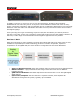
Overview CR QMOD™ technology is opening the door to new HDTV applications. Thanks to CR innovation, broadband RF over coax isn’t just for TV anymore. The broadband network that exists in many sports, commercial, education, and civic facilities can be re-tasked for distribution of in-house highdefinition video and audio from HD satellite and cable receivers, IP and microwave driven media – and digital signage.
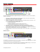
Source Integration HD Component Source The most common application for QMOD technology is to distribute the output of an HD satellite receiver or cable box. Connect the Component YPbPr video between the two units, then either TosLink optical, coax digital or stereo audio outputs to the QMOD.
DirecTV Tips For best performance, go to the receiver’s Setup/HDTV menus and: Go to Video and turn the Native mode Off (otherwise, video can revert to 480p) Go to Resolution and turn off all resolutions but 720p (Native Off doesn’t work in 1080i) VGA Source VGA output is handled differently, for several reasons. Similar to video projection, using a Scaler allows you to format the video exactly how you want it to be seen, instead of off to the left, right, up, down, chopped off, too small or not at all.
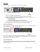
QMOD-HDSC The QMOD-HDSC has an internal scaler, so the setup is much simpler.
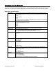
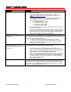
Encoding and RF Settings There are a number of settings you can change via the QMOD front panel. Some are obvious, and some are not so obvious. In most applications, the basic settings will work fine with all displays. Basic Input and RF Settings Video Input Video Format Channel Cable Format RF Level dB Audio Input No Vid Color QAM Type Firmware Contemporary Research Sets the video resolution for the RGBHV/Component inputs. Video and S-Video inputs are automatically set to 480i.
Of course, there are exceptions to every rule that often arise with older displays with archaic firmware, which is why we offer a variety of encoder options and settings. A few examples include: Older LG sets need to see the MPEG stream encoded at 18 mbps (19.4 mbps total). Newer displays don’t need channel data, older sets need to see the CVCT data table. Some displays want to see certain PMT data, while most ignore almost all values.
Basic Troubleshooting Symptom QMOD constantly resets – analog inputs QMOD SDI switches to background color during setup or occasionally. QMOD channel tunes fine connected directly to a TV, but not when combined with in-house RF system. QMOD channel is Green Contemporary Research Solutions Usually, the encoder is resetting because the input video isn’t set to a correct HDTV resolution or frequency. Check if your QMOD has V 4.1 or higher firmware, if not, go to www.crwww.com/downloads.
RF Integration In this section, we will discuss the basics of RF distribution. We encourage integrators to learn more about RF systems, Blonder-Tongue is one company that offers many resources and seminars. In addition, providers such as Toner Cable can offer design assistance, RF distribution components, and testing tools. Channel Architecture In baseband video, such as video cable or Cat5 systems, one cable can carry only one signal.
When the channels for over-the-air TV were created, the FCC had to carve out gaps to avoid conflicts with frequencies that were already assigned. As a result, as you move from Channel 2 upwards, the frequencies jump around a bit. As the easy architecture for creating your own HD cable system is to stay in the low frequencies, it’s important to keep this in mind. Channel 2 3 4 5 6 95 96 97 98 99 14 15 16 17 18 19 20 21 22 7 8 9 10 11 12 13 23 24 25 26 27 28 Freq 57.0 63.0 69.0 79.0 85.0 93.0 99.0 105.
Combining Channels Somewhere at the cable company head end, the company combined all the different cable channel modulators in to one RF delivery system. A Modulator receives an analog or digital video signal on one end, and converts it to single channel on the other. Each modulator can be set to a different channel. Remember those little TV splitters you’ve used to drive one to four TV sets from the same antenna or cable feed? A combiner is the same idea – you just use it the other way.
Using and Measuring RF Output Levels One important fact to understand is that, when combining modulators with other modulators or an incoming cable feed, the amplitude levels of all the sources must be at least roughly the same. That means you need to know what those levels are. If the only sources are multiple QMOD units, just set them all the same level. When combining with cable, you will want to know the level, measured in dBmV.
RF Output Levels and Combiners Note, that when you combine RF channels, there is some loss, called insertion loss. A simple 2input combiner might drop the output a few dB. Larger 8- or more input combiners can drop much more, in the range of -12 to 18 dB. There are also a few active, multi-port commercial combiners that average less loss than similar passive combiners. Your RF supplier can supply insertion loss information for their products.
Distribution and Attenuation If you’re putting together a design for a new RF system, there are several factors to keep in mind. The key difference between RF and typical baseband systems is that you aren’t factoring cable length in terms of cumulative resistance and capacitance over all the cable in the system – it’s an antenna system, not a baseband system. The math is different. Also, you’ll see power speced in terms of dB or dBmV in literature.
Taps Taps are used at the end of the wire in a system, feeding from one to eight TVs. A Tap has an In and an Out port – 18-28 dB taps lose only about 1 dB passing through. The Tap Outs feed each TV subtracting from 18 -28 dB in the process. For example, if the net signal arriving at a 20 dB tap at 25 dBmV, each TV will receive a net +5 dB of signal, fine for digital.
Factoring Levels The aim of your RF design is to deliver at least 0 dBmV for digital, 10 dB for analog to each TV. If your system is totally digital; you have a lot of room to maneuver, about 0 to dB to 25 dB. Analog channels needs are tighter – too low, you lose signal quality, too high it’s over-saturated. We mentioned before that each TV feed is really an isolated wire, and that’s how you look at calculating loss. In the system above, the longest run is 250’, the shortest 225’.
Resources In review, there are several key resources integrators will need to effective in providing HDTV solutions. RF Meter – should be able to test both analog and digital channels, up to 870 MHz Education – The Blonder Tongue Broadband Reference Guide is a must-have “bible” for RF applications, available from Blonder or your RF supplier. Blonder also sponsors basic and advanced seminars for RF design – go to www.blondertongue.
Integrating Control Now that you’ve created an HD delivery system for RF, you can also integrate the displays over the same RF cable using Display Express. In IT terms, Display Express is the control layer of broadband RF. The system inserts a small control signal between channels 4 and 5, combined and carried throughout the system with the rest of the TV channels. The technology will not interfere with other TV channels, and can be carried to thousands of displays via coax cable and fiber.