
User Manual

Contemporary Research 17 QMOD-HD Integration
Factoring Levels
The aim of your RF design is to deliver at least 0 dBmV for digital, 10 dB for analog to each TV. If
your system is totally digital; you have a lot of room to maneuver, about 0 to dB to 25 dB. Analog
channels needs are tighter – too low, you lose signal quality, too high it’s over-saturated.
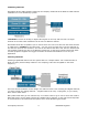
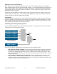
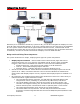
We mentioned before that each TV feed is really an isolated wire, and that’s how you look at
calculating loss. In the system above, the longest run is 250’, the shortest 225’. Usually, you
calculate both, but since this system is very evenly balanced, you just need the high figure.
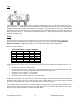
Note that you don’t count the -1 loss at the tap that feeds the TV – that’s what you lose going
through to the next tap. If you have several taps before that point, count them. Factor at the
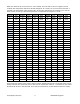
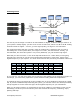
highest frequency in your system - the chart would look like this, assuming a 33 dBmV initial level:
Chan 250’ RG6 Freq Loss Split Total Power Net 18 dB Tap
2 1.5 2 3 3.5 6.5 33 26.5 8.5
28 1.5 3 5.5 3.5 9 33 24 6
70 1.5 4.5 7 3.5 10.5 33 22.5 4.5
137 1.5 6 9 3.5 14 33 19 1
225’
2 1.25 2 2.5 3.5 5.5 33 27.5 12.5
As you can see, you lose more power due to frequency than splitters as the channels go higher. In
this design, you could easily expand the system without needing additional amplification.
In creating the chart, I first figured out the net dB to the TV, then decided on choosing the 18 dB
tap. If you have additional taps extending the system, you can then look to the charts provided by
the tap supplier to see the exact loss figure at the highest frequency for your calculations.
When you do larger systems, it’s a good idea to use an RF supplier or consultant to work out the
final design, but know you know how they solve the elements of frequency, combining, amps,
splitting and taps.