Christian Magg, ADRR 25.09.
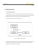
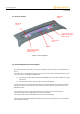
Christian Magg, ADRR 25.09.2019 1. System Overview 1.1. RKE-Module Specifications The RKE-Module is a transceiver module which handles Comfort Access (CA), Keyless Go (KG) and other remote functions. The module receives and controls the signals and work as wireless gateway between transmitter and central electronic module (SAM) in the vehicle. The following figure shows a schematic of the system.
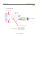
Christian Magg, ADRR 25.09.2019 1.2. Block Diagram RKE Solder pad on PCB Solder pad on PCB Internal switch: only one antenna is activated! Channel 1: 433.47 MHz Channel frequency Channel 2: 434.37 MHz Channel 3: 433.
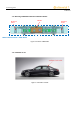
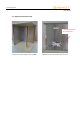
Christian Magg, ADRR 25.09.2019 1.3. Mounting of RKE223E1 inside the Telematics Module RKE AntennaFeeder 1 RKE223E1 MRA2 Telematic module = HOST DEVICE Figure 3: location of RKE223E1 1.4.
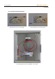
Christian Magg, ADRR 25.09.20199 1.5. Antenna-“System” RKE AntennaFeeder 1 RKE Antenna Feeder 2 “Hole” in crossbar, works together with the Feeder as Antenna-“System” Crossbar, part of the car RKE223E1 “Hole” in crossbar, works together with the Feeder as Antenna-“System” Figure 5: mounting detail 1.6. Antenna-Replacement for homologation The Antenna-Feeder cannot work correctly as transmitting element outside his mounting position on the car.
Christian Magg, ADRR 25.09.20199 1.7.
Christian Magg, ADRR 25.09.20199 1.8.
Christian Magg, ADRR 25.09.20199 1.9.
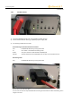
Christian Magg, ADRR 25.09.20199 1.10. Test-box controls 1) Connecting RKE223E1-Module with Test-box (RS232 to MQS cabeling) 2) Connect Test-box with DC cables (eg.
Christian Magg, ADRR 25.09.20199 2. Safety Recommendations WARNING: The Module is designed for in-car use only. It MUST be well integrated into the automotive environment (Tambient min. -40 °C to max. +105 °C) and needs to be installed by the OEM (car-manufacturer) or in case of replacement by a professional garage.