
User's Manual


SIEMENS VDO Automotive AG SV C BC P2 RF TG
FCC ID:KR55WK48089 IC:267T-5WK48089
File: D:\Postzula\Kunden\Mb\W221\FunctionalDiscription_W221.doc Page 3 of 3
List of variants
5WK4 8079 Control unit W221for ECE use
5WK4 8089 Control unit W221 for USA use
5WK4 8193 Ferrite antenna
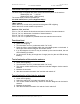
Block diagram
The immobilizer system consists of a control unit, the inductive antennas and the key.
To activate the system, sensors or push-buttons are located in the doors, in the trunk
lid and in the interior. Interaction with the vehicle is effected via the radio receiver in
the control module, which receives the messages from the key and transmits them
via the vehicle's CAN bus to the EZS.
Immobilzer
Control unit
with radio receiver
ID Key
Antennas in the doors, in the
trunk lid and in the bumper
Electronic ignition
starter switch
EZS
CAN bus
Wiring
harnes
s
125 kHz