V4C™ Installation/User Guide Installation/User Guide Internal 1
Table of Contents 1. INTRODUCTION......................................................................................................... 4 2. SYSTEM OVERVIEW ................................................................................................. 5 3. INSTALLATION CHECKLIST ................................................................................... 6 4. V4C EQUIPMENT ....................................................................................................... 7 5. CABLES .......
9.3. ZONAR DISCRETE INPUT SYSTEM CONNECTIVITY........................................................... 22 9.4. SYSTEM SPECIFICATIONS .................................................................................................... 23 9.5. DIMENSIONS ......................................................................................................................... 24 9.6. EXTERNAL GPS ANTENNA (OPTIONAL) .......................................................................... 25 10.
1. Introduction Zonar equipment will provide years of reliable service if properly installed and maintained. Zonar equipment is typically installed in heavy vehicle applications and is often subjected to extreme temperatures, dust, dirt, vibration, and shock. Proper installation is the critical first step to equipment longevity and optimal performance. This guide is meant to be a general guideline for the professional installer and technician.
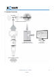
2.
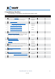
3. Installation Checklist The following is an installation checklist broken down by task.
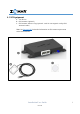
4. V4C Equipment A. V4C Device B. GPS Antenna (Optional) C. GPS Antenna Adhesive Tag (Optional - used for non-magnetic rooftop GPS Antenna installs) Note: See External GPS for detailed information on GPS antenna requirements and recommendations.
5. Cables The V4C has the following primary Types of cables for connecting to the vehicle electrical and data system: Power Cable Diagnostics (vehicle databus) Cables Additionally, there is a fifth, uncommon cable specifically used to wire around battery disconnect systems: Power Cable with Chassis Ground See General Guidelines before you begin. Do not connect power input until all other V4C cables have been connected. 5.1.
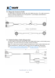
5.2. Diagnostic Connector Cable Use this cable on heavy duty vehicles with SAE J1939 data buses. The cable connects to the 9 Pin Deutsch diagnostic port. The optional 6 - 9 pin adapter (Part# 81632) is available for J1708 connections. 5.3. Vehicle Backbone Cable (Diagnostics) Use this cable on heavy duty vehicles with SAE J1708/J1587 (older) or SAE J1939 (newer) data buses. The cable connects to the data network backbone.
5.4. Power Cable with Chassis Ground This cable is similar to the standard Power Cable, but it adds a green chassis ground wire. This power cable is only needed for vehicles equipped with negative side battery disconnect switches (typically construction equipment). This cable requires the vehicle to physically move at least 5 MPH for at least 100 feet to properly complete the new installation checkout.
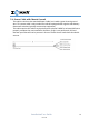
6. Power Wiring and Cable Management The Basic Power Cable is used on Non-J1708/J1939 and non-OBDII installs. It is also used on J1708/J1939 installs with switched power issues (as indicated by flashing “Status” LED with engine running). See General Guidelines and the following requirements. 1) All power leads must be connected to the vehicles protected circuitry (for example, the fuse panel and circuit breaker panel protected circuits).
If power cabling is not connected and powered as described in the Power Bundle Wiring section, one or more of the following conditions may occur. Contact Zonar Customer Care for additional information. Cold Start flags (an indicator that a unit lost and regained constant power) Inaccurate idle and stop times Inaccurate hour meter data Inaccurate mileage data Missing path data or straight line path segments 6.2.
6.3. Wiring Guidelines The wiring guidelines in this section are for unterminated power and ground leads. The authorized method for power termination on the Zonar V4C system is the use of Add-aCircuit fuse taps. Whenever possible, use fuse taps for power termination. If, due to the particular make/model/year of the vehicle being installed, fuse taps cannot be used then the poke and weave method of termination can be utilized.
6.5. Poke and Wrap Installation If it is not possible to use Add-a-Circuit fuse taps, then the poke and weave method can be used. 1) Locate the proper wire where the poke and weave method is to be installed. Strip 3/4” to 1” of insulation from the wire in the vehicle to be installed. Spread the wire strands apart as shown below. 2) Strip 1” to 1 1/2” of insulation from the wire in the fused link to be installed. 3) Insert the wire from the fused link into the spread wire in the vehicle.
7. General Guidelines The following is list of general guidelines for the installation process. It is important to read these before starting. 7.1. Layout V4C unit must be located a minimum of 25 cm (10 inches) from any person. Do not place Zonar RFID tags, cables, or other equipment in any location or position which may compromise human or equipment safety. Verify placement acceptability with State DOT/Law enforcement prior to installation.
7.4. Cable Management Strain relieve and support all cable installations. Avoid sharp bends and tight radius installations of cables. Avoid moving components (for example, doors, steering shafts, handles, fans, etc.). Provide enough cable slack to allow for servicing of equipment (adequate service loop) Avoid routing cables through doors, windows, and other pinch points. Avoid routing cables in high personnel traffic areas. Avoid routing antenna cables near radio and PA equipment. 7.5.
8. V4C Mounting 8.1. Proximity to Persons To comply with FCC RF exposure requirements for mobile transmitting devices, this device must be installed to provide a separation distance of at least 25 cm (10 inches) from all persons. See General Guidelines. 8.2. Device and Asset Information The installation technician must record which V4C unit is being installed in each vehicle.
8.3. Mounting Surface Mount onto an interior flat surface that is large enough to accommodate the footprint. Suggested mounting areas include the following: Horizontal mount on dashboard under an angled windshield free of metallic obstructions Overhead compartment mount with a clear non-metallic view of the sky (for example, under a fiberglass roof or fairing). Note: Verify placement acceptability with state DOT/law enforcement prior to installation. Enclosed areas require an external GPS. 8.4.
8.5.
9. Reference Information and Optional Items 9.1.
9.2.
9.3.
.4. System Specifications o Power DC Input Range: Operating Current: Key off (sleep) Current: 8 – 32 Volts DC 100 mA @12V typ. w/o peripherals; 500 mA with < 1 mA @ 12V o Environmental Operating/storage Temp: Humidity: Test Standards: -40 - 85 95% R.H. non-condensing ISO 16750 o Electrical/EMC: ISO 16750, CISPR 25 o GNSS GPS/GLONASS: SBAS: EGNOS/MSAS/QZSS/WAAS/GAGAN o Cellular LTE Cat 4: 3G/2G fallback: Bands 2, 4, 5, 12, 13 Bands 2, 4, 5 o Wi-Fi: 802.11ac o Bluetooth: 5.
9.5.
9.6. External GPS Antenna (Optional) External antennas are generally only necessary if the V4C GPS unit is enclosed in a radio signal interfering area (e.g. metallic box, under seats, on dashboards with flat windshields, and in cabs or cockpits constructed primarily from metallic material). The suggested installation point is the centerline of the vehicle roof, with minimal cable run to prevent wind and car wash damage.
o Optional GPS Antenna Adhesive Tag (for non-magnetic mounting surfaces) Whenever possible, avoid installing adhesive in cold, wet, or damp conditions. Ideal application range is: 70˚F to 100˚F (21˚C to 38˚C). Clean and dry the surface prior to placement to obtain optimum adhesion. The best surface cleaning solvent is an isopropyl alcohol/water mixture (rubbing alcohol). Remove the backing from the peel and stick to the surface.
11. Limited Warranty LIMITED WARRANTY: Zonar warrants that the Hardware provided under this agreement is free from all material defects in workmanship under normal use and service.
The above warranty periods run from the date of shipment. Provided that the Hardware is used and handled as intended, Zonar will replace any failed or functionally impaired Hardware with equivalent Hardware in terms of performance and functionality. This warranty does not apply to any Hardware that has been misused, altered, willfully abused or that has been damaged due to improper installation by the customer. Hardware installations must follow Zonar’s equipment specific installation guidelines.
Warning: (Part 15.21) Changes or modifications not expressly approved by Zonar Systems could void the user's authority to operate the equipment. Caution: RF Exposure (OET Bulletin 65) To comply with FCC RF exposure requirements for mobile transmitting devices, the antenna(s) used for this transmitter must be installed to provide a separation distance of at least 25 cm (10 inches) from all persons and must not be co-located or operating in conjunction with any other antenna or transmitter.
The hint for usage of CE sign Production plant of V4C Approval owner of V4C Continental Automotive Hungary Kft Continental Automotive GmbH Napmatka u. 6 Heinrich-Hertz-Str.45 H- 1106 Budapest 78052 Villingen-Schwenningen Hungary Germany 12. Legal Information This manual is subject covered by copyright, and all rights are reserved, noting that current Zonar customers may reproduce this manual for their internal business use only, and only during the term of their contract with Zonar.
Zonar Systems. RAM and Wi-Fi are third party trademarks of National Products Inc. and Wi-Fi Alliance respectively. All Rights Reserved.