
CX Series Installation Sheet


2
11
1. Before installing the
CCXX33000000GGSS DDuucctteedd AAiirr PPuurriiffiieerr
, inspect for any signs of
damage.
2. During handling and installation, take care to protect the honeycomb core of
the photo-catalytic module. The titanium-aluminum core is very fragile and
easily damaged.
3. Do not install insulation within 3 inches (75 mm) of the ultraviolet UVC lamps.
4. Access for service is required when mounting the
CCXX33000000GGSS
above ceilings
or behind walls.
5. Do not install in such a manner that the interior photo-catalytic module may
fall from an elevated position, and cause injury to people or equipment below.
1. Unplug the power cord from the
CCXX33000000GGSS
unit.
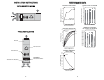
2. Unscrew the two locking knobs and remove the door. (Fig. 6)
3. Remove old filter and replace with new MERV-11 electrostatic filter. Ensure
that airflow arrow on filter points to the inside of module. (Fig. 7)
RREESSEETTTTIINNGG SSEERRVVIICCEE LLIIGGHHTTSS
On the right side of the service panel, there are arrows pointing to two small holes
marked ‘RESET’. (Fig. 8) One is for the FILTER service light, and the other is for
the LAMP service light. The service lights may be reset by inserting the end of a
paper clip into the corresponding hole, and pushing lightly until the service light
returns to green.
LAMP
OK
FILTER
SERVICE
SOON
SERVICE
NOW
RESET
RESET
FFiigg.. 66 FFiigg.. 77
SSEERRVVIICCEE PPAANNEELL
FFiigg.. 88
MMAAIINNTTEENNAANNCCEE
RREEPPLLAACCIINNGG FFIILLTTEERR
IINNSSTTAALLLLAATTIIOONN IINNSSTTRRUUCCTTIIOONNSS
BBEEFFOORREE IINNSSTTAALLLLAATTIIOONN
IINNSSTTAALLLLAATTIIOONN
1. Unscrew the two locking knobs and remove the inner module from the outer
case.
2. Take care not to bend or distort the outer metal enclosure.
3. Ensure the unit is positioned so that the inlet, or return, air enters the side
containing the MERV-11 electrostatic filter. (Fig. 1)
4. Mount the outer case to the support plenum. CAUTION: Use a screw length
that will not penetrate the inside module containing the photo-catalytic mod-
ule and MERV-11 electrostatic filter. There is only 1/2 inch of clearance
between the outer case and inner module.
5. In the event the foot print of the air handler is larger or smaller than the outer
metal enclosure of the
CCXX33000000GGSS
unit, suitable metal transitions should be
fabricated from 18 ga. sheet metal. (Fig. 2)
6. Tape all seams between the air handler and the outlet side of the
CCXX33000000GGSS
to ensure there can be no air bypassing the system.
7. Attach the air handler to the outlet side of the
CCXX33000000GGSS
with #10 x 3/8 self-
drilling sheet metal screws.
8. Slide the inner module into the outer case, and secure locking knobs finger
tight only. Ensure the inner module can slide freely in and out of the outer
case.
9. Plug the power cord into any 120 VAC outlet, and check both sight ports to
ensure both lamps are illuminated. The ultraviolet lamps must remain on at
all times.
10. Check the
CCXX33000000GGSS
service panel. The LED service lights should flash in
sequence for 15 seconds. The FILTER light should then turn flashing green,
and the LAMP light a steady green.
11. Set the HVAC fan to operate for at least 30 minutes every hour. If air quality
problems persist after one week, increase the fan operating time by 5 minute
intervals, until suitable air quality is achieved.