
Operating instructions


25
W415-0680 / 04.10.08
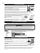
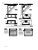
RESTRICTING VERTICAL VENTS
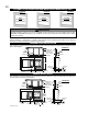
BCDV42CF ONLY: Vertical terminations may display a very ac-
tive fl ame. As this appearance is not desirable, the vent exit must be
restricted using restrictor plate, W500-0205. This reduces the velocity
of the exhaust gases, slowing down the fl ame pattern and creating a
more traditional appearance. The plate has a series of holes to allow
for adjustment.
Remove the two screws on either side of the exhaust collar inside the
fi rebox. Install the plate as shown. Install the plate on the desired set of
holes then replace the screws.
TOP OF THE
FIREBOX
FLUE COLLAR
RESTRICTOR PLATE
FIGURE 64
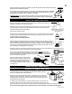
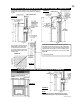
GAS INSTALLATION
Proceed once the vent installation is complete.
NOTE: All gas connections must be contained within the fi replace when complete.
1. Move the fi replace into position and secure to the fl oor through the 1/4" holes located at either side of the base.
2. The fi replace is designed to accept 3/8" gas supply line. The fi replace is equipped with a 3/8" manual shut-off valve.
3. Connect the gas supply in accordance to local codes. In the absence thereof, install according to the National Installation Code.
4. When fl exing any gas line, support the gas valve so that the lines are not bent or kinked.
5. Check for gas leaks by brushing on a soap and water solution.
DO NOT USE OPEN FLAME.
Purge all gas lines with the glass door of the stove removed. Assure that a continuous gas fl ow is at the burner before re-install-
ing the door.
FIGURE 65
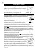
For remote wall switch and decorative light installations for the BCDV36CFG see section "BCDV36CFG SWITCH/WIRING
DIAGRAM".
For ease of accessibility, an optional remote wall switch may be installed in a convenient
location. A 20ft length of millivolt wire is connected to the gas valve for the wall swtich.
However, if a greater length is required route 2-strand (solid core) millivolt wire through
the electrical hole located at the bottom left side of the unit. The recommended maximum
lead length depends on wire size:
WIRE SIZE MAX. LENGTH
14 gauge 100 feet
16 gauge 60 feet
18 gauge 40 feet
Do not connect either the wall switch, thermostat or gas valve directly to 110 volt electricity. Attach the two leads to
terminals 1 and 3 located on the gas valve.
OPTIONAL WALL SWITCH INSTALLATION EXCLUDING BCDV36CFG
This appliance may be installed as an OEM (Original Equipment Manufacturer) Installation in a manufactured home or mobile home
and must be installed in accordance with the manufacturer's instructions and the Manufactured Home Construction and Safety Stand-
ard, Title 24 CFR, Part 3280, in the United States or the Mobile Home Standard, CAN/CSA Z240 MH Series, in Canada. This appli-
ance is only for use with the type(s) of gas indicated on the rating plate. A conversion kit is supplied with the mobile home appliance.
This Mobile/Manufactured Home listed appliance comes factory equipped with means to secure the unit.
The fi replace is equipped with two 1/4" diameter holes located in the front left and right corners of the base. For mobile home instal-
lations, the fi replace must be fastened in place. Use #10 screws, inserted through the holes in the base to secure.
Always turn off the pilot and the fuel supply at the source, prior to moving the mobile home.
After moving the mobile home and prior to lighting the fi replace, permanently ensure that the logs are positioned correctly.
This appliance may be installed in an aftermarket permanently located, manufactured (mobile) home, where not prohib-
ited by local codes.
This appliance is only to be used with the type of gas indicated on the rating plate. This appliance is not convertible for
use with other gasses, unless a certifi ed kit is used.
CONVERSION KITS
The mobile home appliance is fi eld convertible between Natural Gas (NG) and Propane (LP).
To convert from one gas to another consult your Authorized® dealer/distributor.
MOBILE HOME INSTALLATION