MATE System Controller and Display Installation and User Manual for the OutBack MATE and MATE 2
Warranty Dear OutBack Customer, Thank you for your purchase of OutBack products. We make every effort to assure our power conversion products will give you long and reliable service for your renewable energy system. As with any manufactured device, repairs might be needed due to damage, inappropriate use, or unintentional defect. Please note the following guidelines regarding warranty service of OutBack products: • Any and all warranty repairs must conform to the terms of the warranty.
Disclaimer UNLESS SPECIFICALLY AGREED TO IN WRITING, OUTBACK POWER SYSTEMS: (a) MAKES NO WARRANTY AS TO THE ACCURACY, SUFFICIENCY OR SUITABILITY OF ANY TECHNICAL OR OTHER INFORMATION PROVIDED IN ITS MANUALS OR OTHER DOCUMENTATION. (b) ASSUMES NO RESPONSIBILITY OR LIABILITY FOR LOSS OR DAMAGE, WHETHER DIRECT, INDIRECT, CONSEQUENTIAL OR INCIDENTAL, WHICH MIGHT ARISE OUT OF THE USE OF SUCH INFORMATION. THE USE OF ANY SUCH INFORMATION WILL BE ENTIRELY AT THE USER’S RISK.
Contents INTRODUCTION MATE Specifications and Features Manual Setup Installation 1 Basic Operation Power Up MAIN Screen How to Read a MATE Screen Screen Types 2 MATE Setup Setup the MATE Setting the Clock Contrast Adjustment Backlight Adjustment 3 MATE Communications Options Communications Options Communications Errors Errors and Debugging 4 MATE Summary Screens FX Summary Screen Charge Controller Summary Screen Summary Screen Options 5 MATE Status Screens FX Status Screens Charge Controller Screens 6 MATE
Grid-Use Mode Weekday Grid-Use Start Weekday Grid-Use Stop Weekend Grid-Use Start Weekend Grid-Use Stop MATE DEFAULTS 8 MATE Menu Map Menu Structure MATE Menu Guide MATE Menus MATE Menu Map Overview APPENDIX Troubleshooting User Information and Settings Warranty Product Registration 91 93 94 95 95 96 100 101 103 105 119 121 124 125 126 127
Introduction The OutBack Power Systems MATE serves several functions: • Displays and configures the system and its components—the FX Series Inverter/Charger, the FLEXmax 80 Charge Controller*, and the FLEXnet DC • Coordinates system operation, maximizes performance, and prevents multiple products from conflicting • Permits exact adjustments of your power system through a series of convenient display screens, which allow switching among different components, viewing the status of each and changing settings *
MATE Specifications • Communication Protocol: proprietary OutBack multi-drop network • Interconnecting Cable: CAT 5 (8 IATIA 518B) PC non-crossover network cable • Maximum Cable Length Successfully Tested: 1000 feet (300 meters) of cable in an office/ commercial building NOTE: Signal degradation can result if cable is run in conduit with AC wiring or in other electronically “noisy” environments; these can affect the maximum length the cable can run without incurring transmission errors.
With the MATE, a user can know the system’s activity and conditions at any given time. Sometimes, after careful observations, a user might want to change the conditions or set points which cause an action to occur. What is a set point? A set point is a condition, measurement, or baseline a user establishes in order for something else to happen. A home thermostat offers a simple example.
Manual Setup The MATE is a micro-computing device which means it is less powerful and smaller in size than a personal computer. A user will often scroll through a series of MATE screens in order to view the system status or change system conditions. This manual will show all the MATE screens and tell what they do. • Chapters 1-5: setting basic items and display options (when, how, and what you want to view) with the “soft keys,” enabling the user to get around the MATE and change its settings.
To Install the MATE: • • • • • • • Install all other OutBack components first. Run the CAT 5 cable from the source (HUB, FX or Charge Controller) to the MATE’s location. Connect the CAT5 cable to the source but not to the MATE just yet. If connecting a computer to the MATE or MATE2, run a serial cable from the computer to the MATE’s location, but do not connect the cable at this time. Unsnap the MATE’s back plate and find the four screw holes. If a MATE2 version is used, the back cover need not be removed.
1 12 Basic Operation
NOTE: For a viewing of all MATE screens, please see pages 105-118 at the end of this manual. Power Up A soon as the MATE cable is plugged into a powered OutBack product, the MATE itself will power-up and display several information screens. G’day Mate (C) 2007 OutBack Power Systems Version Code a.aa Serial #xxxxxxxx Screen EE b.
Searching for Devices FX Found Fourth screen (one of the following): t The MATE found an FX Series Inverter/Charger t The MATE has found a Charge Controller t The MATE has found the HUB t Port Assignment screen follows the HUB Found screen Each Port used will show its connected component.
No Device Found Would you like to Retry? YES NO NOTE: If the MATE does not find the connected device, refer to page 124, Troubleshooting MAIN Screen MAIN--------------------------------12:17:04P SUM STATUS SETUP SUMMARY shows the direction and amount of power flow in regard to inverting, charging, selling, and/or pass through. It also shows the voltage of the battery.
Press the first two soft keys from any screen to return to the MAIN screen. MAIN--------------------------------12:17:04P MAIN--------------------------1:35:04p SUM STATUS SETUP ADV SUM STATUS SETUP ADV Navigation This section of the manual will cover how to use the buttons on the MATE to navigate the menus.
How To Read a MATE Screen MATE screens will either show values that can be changed or navigate to value screens. The information on the MATE’s screen is segregated by type or task and distinguished by location on the screen and the choice of lowercase or uppercase letters. Occasionally it can be misread by a user. The following example is shown for clarification.
t t t t LOCATION—the top line, STATUS/FX/METER-----P01 (the HUB’s first Port) indicates STATUS then FX then METER have been selected from the MAIN screen. Pressing the or soft keys displays the different METER screens. Pressing the soft key advances the Port number if there are other devices connected to the HUB. If no HUB is present, this will read “P00”. LABEL—the screen’s left side shows a condition, system feature, or measurable event.
Although the OutBack MATE menu display screens vary depending on the unit’s software version, the menu structures and navigation are the same for all versions. The MATE uses a branching menu structure to display various OutBack products’ operation modes and statuses. The menus are divided by product type and are categorized by either type of settings or the information being displayed as shown in the following example.
2 20 MATE Setup
Setup the MATE MAIN--------------------------------9:57:32A SUM STATUS SETUP ADV SETUP------------------------------choose device: FX CNT GLOW PG2 SETUP/MATE/PAGE2-------------choose category: PG1 Press the soft key. MATE SETUP/MATE/PAGE 1-------------mate code rev: 402 choose category: CLOCK Start with the screen, which appears after the power-up screens, and press the soft key. SUMRY COMM This screen displays the MATE’s code version and some SETUP choices.
Setting the Clock Why you want to do it: Certain functions—such as when to use grid-supplied power (Grid-Use Mode) or generator (Advanced Generator Start Mode)—are dependent on accurate time and date settings. Otherwise, the system will never work optimally. SETUP/MATE/PAGE1-------------mate code rev: 402 choose category: CLOCK CNT GLOW PG2 SETUP/MATE/CLOCK-------------Tu 1/01/03 12:00:00P BACK DATE TIME Choose from the SETUP/MATE/ PAGE1 SETUP choices screen.
Current Day Mo 9/26/07 INC DATE SET YEAR changes the day of the month. Press the soft key after changing the date. The next screen adjusts the year ADJUST DATE AND THEN YEAR Current Year Mo 9/26/07 INC DEC YEAR YEAR DONE or changes the year setting. Press the soft key after the date change is final. This returns the MATE to the SETUP/MATE/CLOCK screen.
Contrast Adjustment Why you want to do it: Everyone has different eyesight and ambient lighting varies with every location of a MATE. Like any other monitor, you may want to adjust the lighting and contrast for easier reading.
Backlight Adjustment PATH MAIN-----------------------------------9:57:32A SUM STATUS SETUP------------------------------choose device: SETUP ADV FX MATE SETUP/MATE/PAGE1-------------mate code rev: 402 choose category: CLOCK CNT GLOW PG2 Choose from the SETUP/MATE/PAGE 1 Setup choices screen: SETUP/MATE/PAGE1-------------mate code rev: 402 Choose Category CLOCK CNT GLOW PG2 On the SETUP/MATE/GLOW screen, pressing the soft key brings up three backlight settings: t LEVEL t MODE t TIME SE
3 26 MATE Communications Options
Communications Options Why you want them: The MATE communicates commands to different components. It needs to be aware of any newly added or moved devices so it can recognize them. An error reading doesn’t mean the system is failing, but that the MATE is looking for a component that has been moved from one HUB Port to another or has been disconnected completely. The MATE is trying to account for the system components.
SETUP/MATE/PAGE2-------------choose category: BACK REPOLL PC DEBUG SETUP/MATE/COMM-------------comm errors: BACK 00:000 03:000 06:001 09:001 VIEW 01:000 04:025 07:001 10:001 RSET 02:000 05:001 08:001 2M:001 SETUP/MATE/COMM-------------comm errors: BACK 28 VIEW To debug the system, press the soft key.
SETUP/MATE/PAGE2-------------choose category: BACK REPOLL PC DEBUG SETUP/MATE/PAGE2-------------PC communications: OFF BACK OFF ON SETUP/MATE/PAGE2-------------choose category: BACK REPOLL PC Press the soft key to enable or disable the MATE’s RS232 communications port. In the PC communications screen, choose ON or OFF by pressing the respective soft key. Press the soft key to return to the choose category screen.
Communication Errors --A COMM ERROR HAS OCCURED MORE INFO VIEW DEBUG The A COMM (communication) ERROR HAS OCCURRED screen appears when a communication error among the components occurs. Errors and Debugging Communication errors (COMM ERR) that occur with OutBack Power Systems components are often the result of loose, damaged, or unplugged cables.
Advancing errors (the count is increasing on the DEBUG screen) mean the HUB is not finding a device that was previously there. In order, try the following: 1. Check that the device’s DC breaker is on and operating correctly, that the device itself is on, and that the CAT5 cable connecting the device to the HUB is plugged in at both ends. Then re-poll the system (SETUP MATE PG2 COMM REPOLL, see page 29) 2. Check the DEBUG screen to confirm the problem is solved. 3.
4 32 MATE Summary Screens
Summary Screens The Summary screens provided by the MATE: • Summarize the current status of any FX, OutBack Charge Controller and/or FLEXnet DC connected to it. • Can be accessed from the screen by pressing the soft key and can be set to pop up like a screen saver after a delay (See Summary Screen Options on the next page for more setup information).
FX Summary Screen FX Total Inverting AC Loads Buying $ 12.6V 97% 0.000kW 0.000kW 0.000kW If the MATE has one or more FXs connected to it and does not have a FLEXnet DC as part of the system, an FX Summary screen will be displayed as the Summary default screen. Otherwise, it will follow the FLEXnet DC summary screens. The FX summary screen’s values summarize power flow in an FX system as well as the nontemperature compensated battery voltage. OutBack Charge Controller Summary Screen CC TOTALS 13.
SETUP/MATE/SUMMARY--------summary control BACK TYPE DELAY ROLL To choose the SUMMARY screen you want to view automatically and also view via the MAIN menu, press the soft key on the SETUP/ MATE/SUMMARY screen. SETUP/MATE/SUMMARY/TYPE--summary Roll screen type Press either the and soft keys to change the summary screen BACK Roll—switches between FX and CC (Charge Controller) summary screens automatically if both are connected to the MATE through an OutBack Power Systems HUB.
SETUP/MATE/SUM/TYPE---------summary CC Only screen type BACK INC DEC SETUP/MATE/SUM/TYPE---------summary DC Only screen type BACK INC DEC SETUP/MATE/SUM/TYPE--------summary DC OnlySimple screen type BACK INC DEC CC Only—displays the CC SUMMARY screen. Pressing the opens the DC Only summary screen. DC Only—displays the DC SUMMARY screen. Pressing the soft key opent the DC Only Simple screen.
MAIN-------------------------------9:57:32A SUM STATUS SETUP ADV Pressing the soft key in the MAIN menu brings up your chosen SUMMARY screen or, if None is chosen, it will bring up the FX SUMMARY screen as a default. To adjust the timing of the SUMMARY screen display, see the next section.
5 38 MATE Status Screens
STATUS Screens Why you want them: Status screens give the user a breakdown of individual activities of the FX Series Inverter/Charger(s) and the Charge Controller(s), including AC and DC voltage and AC current meters. It is these individual readings that combine to produce the Summary screens noted earlier and allow monitoring of the system operation.
Reading a STATUS Screen STATUS/FX/PAGE1--------------choose catagory STATUS/FX/PAGE2--------------choose catagory STATUS/FX/PAGE3--------------choose catagory MODES PG1 PG2 METER BATT PG2 ERROR WARN PG3 DISCON SELL MAIN • MODE: a functioning condition or state of operation • METER: displays inverter and charger activity, including output and input AC voltage, and AC inverter, charger, and input current • BATT: displays the battery temperature, voltage and the various set points for the differ
FX STATUS MODE Screens STATUS/FX/PAGE1-----------------choose category: PG2 STATUS/FX/MODE------------P00 inv control: ON CHANGE DOWN STAT MODE PORT STATUS/FX/MODE-----------P00 ac in control: USE CHANGE DOWN UP MODE PORT STATUS/FX/MODE------------P00 chr control: ON CHANGE DOWN UP MODE PORT STATUS/FX/MODE-------------P00 aux control: AUTO CHANGE DOWN UP MODE PORT STATUS/FX/MODE-------------P00 eq enabled: No CHANGE UP MODE PORT MODES METER BATT STATUS/FX/MODE------------P00 inv control:
FX STATUS METER Screens Charge inv 0.0kw chg 0.0kw P00 zer 0.0kw buy 0.0 kw STATUS/FX/METER---------P00 output 117 vac voltage STATUS/FX/METER---------P00 input 118 vac voltage DOWN STATUS PORT DOWN DOWN UP TOP PORT TOP PORT STATUS/FX/METER------------P00 inverter 0.0 aac current STATUS/FX/METER----------P00 charger 0.0 aac current STATUS/FX/METER--------P00 input 0.0 aac current DOWN DOWN DOWN UP TOP PORT UP TOP PORT STATUS/FX/METER----------P00 sell 0.
FX STATUS Batt(ery) Screens STATUS/FX/MODE-------------P00 battery 13.6 vdc actual STATUS/FX/MODE-------------P00 battery 13.6 vdc temp compensated STATUS/FX/METER-------------P00 battery 14.4 vdc set point DOWN DOWN DOWN STATUS PORT UP TOP PORT UP TOP PORT STATUS/FX/BATT---------------P00 absorb 00.0 hrs time remaining STATUS/FX/BATT---------------P00 float 13.6 vdc set point STATUS/FX/BATT---------------P00 float 24.
FX STATUS ERROR Screens STATUS/FX/PAGE1------------------choose category: MODES METER BATT PG2 STATUS/FX/ERROR----------P00 stacking No error detected DOWN UP TOP PORT STATUS/FX/ERROR----------P00 phase loss No error DOWN UP TOP PORT STATUS/FX/ERROR---P00 ac output No backfeed DOWN UP TOP PORT STATUS/FX/PAGE2------------------choose category: PG1 ERROR WARN PG3 STATUS/FX/ERROR-----------P00 Low ac output No voltage DOWN STATUS PORT STATUS/FX/ERROR----------P00 inverter No overtemp DOWN
FX STATUS WARN(ING) Screens STATUS/FX/PAGE2----------------choose category: PG1 ERROR WARN PG3 STATUS/FX/WARN--------------P00 acin voltage No too high DOWN UP TOP PORT STATUS/FX/WARN-------------P00 temperature No sensor fault DOWN UP TOP PORT STATUS/FX/WARN------------P00 airtemp 190 DOWN UP PORT STATUS/FX/WARN-----------------end of warnings menu UP TOP STATUS STATUS/FX/WARN-------------P00 acin freq No too high DOWN STATUS PORT STATUS/FX/WARN-------------P00 acin voltage No too low DOW
DISCON(NECT) Screens STATUS/FX/DISCON-----------P00 acin freq No too high DOWN STATUS PORT STATUS/FX/DISCON-----------P00 acin voltage No < min DOWN UP TOP STATUS/FX/DISCON----------P00 acin freq No too low DOWN UP TOP PORT STATUS/FX/DISCON---------------end of DISCON menu PORT UP TOP STATUS/FX/DISCON-----------P00 acin voltage No > max DOWN UP TOP PORT STATUS/FX/PAGE3---------------choose category: STATUS PG2 DISCON SELL MAIN DISCON(NECT) Screens • acin freq too high: screen displays
OUTBACK CHARGE CONTROLLER STATUS MODE Screens To view the CC STATUS screens, return to the MAIN Menu, press the soft key and then choose the CC on the STATUS choose product screen. The STATUS screens include MODE, METER, and SET (SET POINT). In STATUS Mode, these Charge Controller functions can be viewed by the MATE, but not changed.
OUTBACK CHARGE CONTROLLER STATUS METER Screens To view the CC STATUS screens, return to the MAIN Menu, press the soft key and then choose the CC on the STATUS choose product screen. The STATUS screens include MODE, METER, and SET (SET POINT). In STATUS Mode, these Charge Controller functions can be viewed by the MATE, but not changed. mode: Silent in 33.2 vdc out 38.
OUTBACK CHARGE CONTROLLER STATUS SETP(OINT) Screens STATUS/CC/SETPT------------P00 Absorb 28.8 VDC DOWN STATUS PORT STATUS/CC/SETPT------------P00 Float 27.2 VDC DOWN UP TOP PORT STATUS/CC/METER----------------end of set point menu UP TOP STATUS Press the first two soft keys simultaneously to return to the MAIN Menu or press and then press on the STATUS screen. NOTE: All OutBack Charge Controller screens are displayed as CC screens on the MATE.
6 50 MATE Hot Keys
HOT KEYS INV Hot Key The INV “hot” key takes you to the INVERTER CONTROL screen allowing direct control of the FX’s inverter from anywhere in the menu system.
AC IN Hot Key The AC IN “hot” key allows direct control of the AC input from anywhere in the menu system. INV Hot MAIN-------------------------1:35:04p SUM STATUS SETUP ADV The yellow LED indicator above the AC IN “hot” key has three settings: u Flashing - an AC source is available, but not connected u Continuously On - the AC source is connected and in use u Off - no AC source is present The number of AC IN key presses determines which menu is called up.
PRESS TWICE: AC INPUT CONTROL currently: USE DROP USE • OK • The GEN START CONTROL screen allows changes to the Advanced Generator Start (AGS) mode. The AGS settings only take effect when Advanced Generator Start is enabled (See the AGS Mode section for more information). NOTE: This does not control the GenAlert function. • When an OutBack HUB is employed, the GEN START CONTROL only affects the FX programmed as the AGS PORT in the AGS setup.
NOTE: The charger’s operation is independent of the inverter. With the inverter in OFF mode, the charger can be set to come on when AC is available, but have the inverter stay off when AC is disconnected. disables all charger functions in the FX. enables automatic battery charging, silent, and “re-float” when an AC input source is connected. also recharges the batteries, but eventually remains in the “float” charging stage (and eliminates silent mode) until the AC input is disconnected.
Pressing on the CHARGER MODE CONTROL screen brings up the EQUALIZE CONTROL screen EQUALIZE CONTROL eq enabled START STOP OK When has been selected, the EQ charge has stopped. EQUALIZE CONTROL eq charge stopped OK MAIN EQ parameters must be set in ADV/FX menu. follow mauf. Recommendations When has been selected, two informational screens are displayed. The user must push the soft key before an equalizing cycle can begin.
To stop an equalizing process, return to the EQUALIZE CONTROL screen and press the soft key. To return to the EQUALIZE CONTROL screen: • Press the hot key four times. • Press the soft key. • Press the soft key on the EQUALIZE CONTROL screen.
7 57 Advanced MATE Menus
MATE Control Modes The MATE, when connected to at least one FX Series Inverter/Charger, offers more sophisticated controls than basic debugging and system displays.
The ADVANCED Menus The MATE must be connected to an OutBack system for the Advanced features to function. MAIN----------------------------------9:57:32 A SUM STATUS SETUP ADV ADV/SETTINGS/WARNING changes made could adversely effect system performance The next screen is a warning screen intended to keep those unfamiliar with an OutBack system from altering the settings. Push any key to advance to the next screen to input the password (141).
ADV-----------------------------------choose device: FX CC DC MATE ADV/MATE/PG1----------------------choose category: HBX GRIDUSE AGS In the ADV menu, push the soft key to view the Advanced MATE functions. PG2 From the ADV/MATE screen, a Control Mode is chosen. Press the soft key to view the HBX screens. HBX Mode What it does: HBX Mode allows control over the use of grid-supplied power based on userdetermined battery voltage and time set points.
HBX Mode: • Stands for high battery transfer • Is used with grid-connected FX Series Inverter/Chargers that have utility power as their AC input • Is a mode primarily used in applications that have enough renewable energy (RE) power production to meet the needs of the loads most of the time • Allows the FX to connect to an AC source if the battery voltage has fallen below a programmable set point for a user configurable amount of time (MATE will then allow the FX to remain connected to the AC source until t
NOTE: HBX Mode will control the Master FX Series Inverter/Charger in Port 1 of a HUB-4 or HUB-10. The Master will then instruct any stacked Slaves to USE or DROP the AC input source (please see appropriate the FX programming manual for stacking instructions). Before starting HBX Mode, set or reset the established values on the four MATE set point modes shown on the following screens: • The first screen, HBX-USE GRID SET POINT appears when the HBX soft key is pressed on the previous ADV/MATE screen.
HBX-Drop Grid Set Point ADV/MATE/HBX--------------------hbx-drop 26.0 vdc grid set point DOWN UP INC DEC This set point shows the voltage—26.0 VDC is the default for a 24V system—at which the FX will DROP its AC input source. The battery voltage must remain above this voltage for the amount of time set by HBX-DROP GRID DELAY (next screen) for a DROP to be issued. Press the soft key to proceed. HBX-Drop Grid Delay ADV/MATE/HBX--------------------hbx-drop 01.
ADV/MATE/HBX---------------------ac input DROP control DROP USE HBX DONE Enable HBX by pressing the soft key. The screen now indicates the MATE is running in HBX mode by displaying the current state, USE or DROP followed by HBX.
AC INPUT CONTROL Currently:USE DROP USE OK Push the hot key to view the AC status and change to USE or DROP as needed. Pressing the soft key means you accept the conditions or mode shown on the screen. MAIN------------------1:35:04p SUM STATUS SETUP ADV NOTE: Even with HBX enabled, the user can issue manual DROP or USE commands using the AC INPUT CONTROL found under the ACIN hot key.
Advanced Generator Start (AGS) Mode This section applies to off-grid systems which regularly use generator-supplied power. Why you may want it: Some systems include fuel-powered generators for either back-up or regular usage. Advance Generator Start Mode sets the conditions under which a generator will automatically start and stop, eliminating inconvenient manual starts and stops.
AGS Setup To enter the AGS setup, go to the screen: Press until 141 and then press MAIN----------------------------------9:57:32 A SUM STATUS SETUP ADV ADV/SETTINGS/WARNING changes made could adversely affect system performance ADV---------------------------------choose device: FX CC DC MATE ADV/MATE/PG1----------------------choose category: HBX GRIDUSE AGS PG2 ADV/MATE/AGS-----------------------choose category: QUIET SETUP TIME 67 VOLT START Press the soft key.
The AGS Setup menu contains the following general settings that define the AGS routines. AGS Port The MATE uses the AUX output of an FX or FLEXnet DC relay to control the generator. The MATE is connected to this FX either directly or through a HUB. If a HUB is used: • Use the and soft keys to set the AGS Port value to the HUB FX or FLEXnet DC Port controlling the generator If no HUB is used and the MATE is directly plugged into an FX, then the AGS Port needs to be set to 0 (zero).
AGS Enabled ADV/MATE/AGS/SETUP-----------AGS enabled: DOWN UP NO NO YES ADV/MATE/AGS/SETUP------------AGS enabled: DOWN UP YES NO YES This is the overall control for the AGS Mode. If AGS is not enabled, none of the AGS settings or controls will work. Enable the AGS first by pressing the YES soft key and then establish your settings. After enabling the AGS Mode, press the soft key to continue to the AGS Control menu.
DC Genset ADV/MATE/AGS/SETUP dc genset DOWN NO UP NO YES In this screen, YES means a DC generator is present and the AGS routine, which normally stops the generator upon the FX going to Float or Silent, will instead stop the generator when the vdc genstop setting is reached. NOTE: If you have a generator that produces AC voltage, maintain the NO status shown on this screen. Press the soft key to go to the vdc genstop screen. VDC Genstop ADV/MATE/AGS/SETUP----vdc genstop: DOWN UP 38.
ADV/MATE/AGS/SETUP----cool down time 0 minutes DOWN UP INC DEC ADV/MATE/AGS/SETUP----warm up time 0 minutes DOWN UP INC DEC After the FX charging has been disabled, the cool down time screen allows the user to adjust the number of minutes the generator will cool down before being shut off. This time should follow the manufacturer’s recommendations.
Generators are an integral part of many renewable energy systems. Setting a generator’s start and stop times and voltage set points can be confusing. The following test helps assure your generator is properly functioning and the programming is accurate (AGS must be set up first in order to perform this test). Before any further programming, confirm that the generator is working properly by manually turning it on and then shutting it off.
PRESS UNTIL 141 AND THEN PRESS ENTER MAIN----------------------------------9:57:32A SUM STATUS SETUP ADV ADV/SETTINGS/WARNING changes made could adversely affect system performance ADV/PASSWORD--------------------enter the password ENTER INC 131 DEC EXIT ADV---------------------------------choose device: FX CC DC MATE ADV/MATE/PG1--------------------choose category HBX GRIDUSE AGS PG2 ADV/MATE/AGS---------------------choose category: SETUP QUIET TIME VOLT START Go to the ADV/MATE scr
WEEKDAY QT START--------------adj hour 12:00A DOWN INC DEC WEEKDAY QT START---------------adj min 12:00A DOWN INC DEC ADV/MATE/AGS/QT-----------------weekday: 12:00A quiet time start DOWN AGS and adjust the weekday start hours. When finished, press the soft key. and adjust the weekday start minutes. When finished, press the soft key. This will return you to the ADV/MATE/AGS/QT weekday quiet time start menu.
Weekend Start ADV/MATE/AGS/QT-----------------weekend: 12:00A quiet time start DOWN UP CHANGE WEEKEND QT START--------------adj hour 12:00A DOWN INC DEC WEEKEND QT START---------------adj min 12:00A INC DEC DONE ADV/MATE/AGS/QT-----------------weekend: 12:00A quiet time start DOWN 75 UP CHANGE weekend quiet time start is the beginning of the quiet time period for Saturday and Sunday. Most AGS start conditions will be stopped during this time.
Weekend Stop ADV/MATE/AGS/QT-----------------weekend 12:00A quiet time stop DOWN UP CHANGE WEEKEND QT STOP----------------adj hour 12:00A DOWN INC DEC WEEKEND QT STOP---------------adj min 12:00A INC DEC DONE ADV/MATE/AGS/QT--------------weekend 12:00A quiet time stop DOWN UP CHANGE ADV/MATE/QUIET TIME----------end of QUIET TIME menu UP TOP 76 AGS weekend quiet time stop is the end of the quiet time period for Saturday & Sunday. adjusts the hour and minutes settings.
Voltage Start There are three voltage start set points in AGS Mode that the user can adjust. After a generator is started due to a Voltage Start setting, it will be stopped when the FX completes the absorb charge or based on the VDC Genstop setting in the AGS Setup menu previously explained. NOTE: If the DC Genset is set to YES, the generator will only stop after the battery voltage has reached the VDC Genstop voltage for 15 minutes.
2-Minute Voltage Set Point ADV/MATE/AGS/VSTART----------volt start 22.0 vdc 2 min setting DOWN UP INC DEC ADV/MATE/AGS/VSTART----------end of VOLTAGE START menu UP TOP If the battery voltage falls below this set point, a 2-minute timer starts to count down. Upon reaching zero, a start command is sent to the generator even if it is currently Quiet Time. Use the and soft keys to change the default settings. When finished, press the soft key to go to the end of VOLTAGE START menu.
To open the Load Start screen: ADV/MATE/AGS----------------------choose category SETUP QUIET VOLT TIME START PG2 ADV/MATE/AGS/PG2---------------choose category PG1 LOAD START MUST RUN Go to the ADV/MATE/AGS screen and press the soft key. At the ADV/MATE/AGS/PG2 screen, press the soft key.
Load Stop KW ADV/MATE/AGS/LS----------------load stop DOWN 0 kw UP INC DEC An AGS stop command will be issued when the total AC load of all the FXs connected to the MATE falls below this setting for the amount of time set with load stop delay (next screen) as long as the generator was started due to Load Start. This setting excludes any FX charger current for its AC load calculation. The setting can be changed using the and soft keys.
Must Run Why you might want it: In time, a user can determine patterns in energy usage and demands on batteries. Must Run times the generator usage to the heaviest user demands during a day, thus avoiding depleting the batteries or requiring a long recharging period. This might happen in the mornings or early evenings when a family’s power demand is higher. Must Run Time is a daily time period when the MATE commands the generator to run.
ADV/MATE/AGS/MR---------------weekday: 12:00A must run start time DOWN AGS CHANGE weekday must run stop time is the end of the Must Run time period for Monday-Friday. Press the soft key to go to the weekday must run stop screen.
Weekend Start ADV/MATE/AGS/MR---------------weekday 12:00A must run stop time DOWN UP CHANGE ADV/MATE/AGS/MR----------------weekend 12:00A must run start time DOWN UP CHANGE WEEKEND MR START adj hour DOWN INC 12:00A 12:00A Adjust the weekend must run start minutes using the and soft keys. Press the soft key to return to the ADV/MATE/ AGS/MR weekend must run stop time screen when finished.
ADV/MATE/AGS/MR----------------weekend 12:00A must run start time DOWN UP Press the soft key to go to the ADV/ MATE/AGS/MR weekend must run stop screen.
ADV/MATE/AGS/MR--------------end of MUST RUN menu UP TOP AGS ADV/MATE/AGS/PG2----------------choose category PG1 LOAD START MUST RUN PG3 ADV/MATE/AGS/PG3---------------choose category PG2 AGS INC DEC ADV/MATE/AGS/%SOC-------------%SOC stop 90% DOWN AGS INC DEC ADV/MATE/AGS/%SOC-------------end of %SOC START menu UP 85 Press the soft key to access the ADV/MATE/ AGS/PG3 screen which includes the EXERCISE option. Press the <%SOC> soft key.
ADV/MATE/AGS/PG3--------------choose category PG2 %SOC START TIMERS PG4 ADV/MATE/AGS/TIMERS-----------agsstate 0 DOWN AGS ADV/MATE/AGS/TIMERS ---------agsgenfault 0 DOWN UP ADV/MATE/AGS/TIMERS--------24 hr 1440 min vs time DOWN UP ADV/MATE/AGS/TIMERS--------2hr vs time 120 min DOWN UP ADV/MATE/AGS/TIMERS--------2 min 2 min vs time DOWN UP Press the soft key to view the various AGS timer-related screens.
ADV/MATE/AGS/TIMERS--------lsstart timer 0 min DOWN UP ADV/MATE/AGS/TIMERS--------lsstop timer 0 min DOWN UP ADV/MATE/AGS/TIMERS--------vdcstop timer 0 min DOWN UP ADV/MATE/AGS/TIMERS--------exstop timer 0 min DOWN UP ADV/MATE/AGS/TIMERS---------end of TIMERS menu UP 87 TOP AGS This screen displays the load start delay timer which is adjustable up to 240 minutes, counting down.
ADV/MATE/AGS/PG3--------------choose category PG2 %SOC START TIMERS PG4 Press the soft key ADV/MATE/AGS/PG5-------------choose category PG2 EXERCISE ADV Press the soft key. This takes you to the ADV/MATE/AGS/EX (exercise) screen for running a lightly used generator at least one day a month to assure it’s in good working order (see next section). Generator Exercise Why you might want it: Exercising a generator prolongs its life and dependability.
Exercise Start Day (exstartday) ADV/MATE/AGS/EX----------exstartday DOWN AGS INC DEC Use the or soft keys to choose the day (Sunday-Saturday) of the week to exercise the generator. To disable the exercise function, push either the or soft keys until a broken line (--) appears. Press the soft key to go to the EX START TIME screen which sets the exercise start time.
ADV/MATE/AGS/EX-----------------ex start time 12:00A DOWN UP CHANGE Ex Period ADV/MATE/AGS/EX-----------------ex period DOWN 30 min UP INC DEC ADV/MATE/AGS/EX-----------------end of exercise menu UP 90 TOP AGS Press the soft key. This takes you to the ADV/MATE/AGS/EX ex period screen, which allows you to set the number of minutes your generator will run during its exercise period.
Grid-Use Mode Why you might want it: Grid-connected systems make use of utility-supplied power. The MATE’s Grid-Use Mode allows the user to pre-determine the time periods it uses the grid. NOTE: The FX’s default settings are for a generator-supported system. If your system includes a utility’s grid, set the FX to Grid by going to SETUP/FX/INPUT ac transfer control and pressing the soft key.
Example #2: Weekday Start-6:00 p.m. Weekend Start-4:00 p.m. Weekday Stop-6:00 a.m. Weekend Stop-8:00 a.m. • Monday—Thursday evenings at 6:00 p.m., the MATE will issue a USE command to the FX allowing the AC input source to be used. • Monday—Friday at 6:00 a.m., a will be issued. On Friday evening at 6:00 p.m., a USE will be issued. • The following morning is a weekend (Saturday) so a DROP command will be issued at 8:00 a.m. During Saturday afternoon at 4:00 p.m.
ADV-----------------------------------choose device: FX CC DC MATE ADV/MATE-------------------------choose category: HBX GRIDUSE AGS ADV OFF Press the soft key on the screen. PG2 ADV/MATE/GRIDUSE--------------griduse enable: Off DOWN On the ADV menu, push the soft key. ON The first GRID-USE screen to appear is the griduse enable screen. This screen turns GRIDUSE mode ON or OFF. NOTE: Set all the weekday and weekend timing first before turning the GRID-USE Mode on.
WEEKDAY GRIDUSE START adj hour 12:00A DOWN INC DEC WEEKDAY GRIDUSE START adj min 12:00A INC DEC DONE ADV/MATE/GRIDUSE----------------weekday 12:00A griduse start time DOWN UP and set the hour to the desired time. Press to access the adj min screen. and set the minutes to the desired time. Press the soft key to return to the weekday griduse start screen. Press the soft key to access the ADV/ MATE/GRIDUSE weekday grid-use stop screen.
Weekend Grid-Use Start ADV/MATE/GRIDUSE---------------weekend 12:00A gridusestart DOWN ADV OFF ON This setting is the time during the weekend (Saturday and Sunday) that a
MATE DEFAULTS The MATE comes with factory default settings for its various functions. Many of these can be changed depending on a user’s preferences. To return the MATE to its default settings, go to the ADV/MATE/DEFAULT screen and press the soft key. Press the soft key in the ADV/MATE/RESET ARE YOU SURE? screen to reset the default values.
MATE ADVANCED Default Values • HBX Menu ADV/MATE/HBX-------------------hbx-use 12.0 vdc grid setpoint ADV/MATE/HBX-------------------hbx-use 01.0 hrs grid delay ADV/MATE/HBX-------------------hbx-drop 13.0 vdc grid setpoint DOWN DOWN DOWN ADV INC DEC ADV INC INC DEC ADV INC DEC NOTE: The MATE’s hbx-use grid setpoint screen vdc value will equal the battery voltage of the system it’s connected to. In this case, it reflects 12 VDC batteries. ADV/MATE/HBX--------------------hbx-drop 01.
• AGS QUIET TIME Menu ADV/MATE/AGS/QT---------------weekday 12:00A quiet time start DOWN AGS CHANGE ADV/MATE/AGS/QT---------------weekday 12:00A quiet time stop DOWN UP CHANGE ADV/MATE/AGS/QT-----------------weekend 12:00A quiet time start DOWN UP CHANGE ADV/MATE/AGS/QT-----------------weekend 12:00A quiet time stop DOWN UP CHANGE • AGS VOLT START Menu ADV/MATE/AGS/VSTART---------volt start 12.2 vdc 24 hr setting ADV/MATE/AGS/VSTART----------volt start 11.
• AGS MUST RUN Menu ADV/MATE/AGS/MR---------------weekday 12:00A must run start time DOWN AGS CHANGE ADV/MATE/AGS/MR---------------weekday 12:00A must run stop time DOWN UP CHANGE ADV/MATE/AGS/MR---------------weekend 12:00A must run start time DOWN UP CHANGE ADV/MATE/AGS/MR----------------weekend 12:00A must run stop time DOWN UP CHANGE • AGS EXERCISE Menu ADV/MATE/AGS/EX----------------exstartday ---- ADV/MATE/AGS/EX----------------ex start time 12:00A ADV/MATE/AGS/EX----------------ex perio
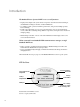
8 100 MATE Menu Map
Menu Structure Yellow Status Indicator, AC Input LED Dedicated Inverter Control “Hot Key” Green Status Indicator, Inverter LED MAIN--------------------------1:35:04p SUM STATUS SETUP ADV Inverter “Hot Key” Four “Soft Keys” The menu system displayed on the MATE will vary depending on the software version the MATE was programmed with at the time of manufacturing or during its last software upgrade.
MAIN--------------------------------9:57:32 A SUM STATUS SETUP ADV STATUS-------------------------------choose device: FX CC DC MATE STATUS/FX/PG1 ----------------P01 choose category: MODES METER BATT PG2 STATUS/FX/BATT--------------P01 battery actual DOWN 102 25.0 vdc STATUS PORT The top line of the MATE display will show the ‘path’ to the current menu; in this example it is STATUS/FX/BATT--------P01 with “P01” referring to the first port of the HUB.
The MATE features over 400 screens for viewing power system status and adjusting its values. The screens are accessible in a series of categorized menus (for example, METERS, WARNING, BATTERY, etc.). By knowing the categories, it’s easier to find a specific screen.
Before entering the ADVANCED screens, a warning message appears. Any changes can always be undone, different values entered, or the MATE can be returned to its factory default settings. After pressing the soft key until the password number 141 appears, the advanced screens for the FX. Charge Controller, and MATE become available.
MATE MENUS INV HOT KEY INV INVERTER CONTROL currently: ON OFF SRCH ON OK AC IN HOT KEY FX Total 12.6V 97% Inverting 0.000kW AC Loads 0.000kW Buying $ 0.000kW STATUS/FX/MODE---P00 ac in control: USE CHANGE DOWN UP MODE PORT STATUS/FX/MODE---P00 eq enabled: CHANGE UP MODE PORT CC TOTALS 14.5 V AC INPUT CONTROL currently: USE EQUALIZE CONTROL eq enabled: NO Output 0A 0.000kW Today 0.
STATUS/FX/METERS--P00 inverter 0.0 aac current DOWN UP TOP PORT STATUS/FX/PAGE1----choose category: MODES METER BATT PG2 STATUS/FX/BATT-----P00 equalize 02.0 hrs time remaining DOWN UP TOP PORT STATUS/FX/ERROR—-P00 stacking NO error detected DOWN UP TOP PORT STATUS/FX/METERS--P00 charger 0.0 aac current DOWN UP TOP PORT STATUS/FX/BATT-----P00 battery 25.0 vdc actual DOWN STATUS PORT STATUS/FX/BATT-----P00 batt temp.
WARNINGS STATUS/FX/WARN---P00 ac input NO current exceeds max DOWN UP TOP PORT MAIN---------------6:54:42PM STATUS/FX/WARN---P00 temperature NO sensor fault DOWN UP TOP PORT STATUS-------------choose device: STATUS/FX/WARN---P00 internal comm NO error detected DOWN UP TOP PORT STATUS/FX/PAGE1----choose category: MAIN---------------6:54:42PM MODES METER BATT PG2 SUM STATUS SETUP ADV STATUS/FX/PAGE2----choose category: STATUS-------------choose device: MODES METER BATT PG2 STATUS/FX/WARN---P00 in
MODES LOGS SUM STATUS SETUP ADV STATUS/CC/METER-P00 CC firmware revision 0001.008.
STATISTICS STATUS/CC/STAT------P01 total kWH DC 307 DOWN UP TOP PORT METER/DC/SHUNT A removed 0AH 0.000kWH DOWN UP TOP SHUNT MAIN---------------6:54:42PM STATUS/CC/STAT------P01 total kAH 0.0 DOWN UP TOP PORT METER/DC/SHUNT A charged 0AH 0.000kWH DOWN UP TOP STATUS/DC/SHUNT A max removed amps 0.6 DOWN UP RESET TOP STATUS/CC/STAT------P01 end of CC stats menu UP TOP STATUS METER/DC/SHUNT B removed 0AH 0.000kWH DOWN UP TOP STATUS/DC/SHUNT A max removed kWatts 0.
STATUS/DC/SHUNT C max removed amps 0.4 DOWN UP RESET TOP STATUS/DC BATT---------total days at 100% 0.7 DOWN UP RESET TOP STATUS/DC BATT---------end of battery status menu UP TOP STATUS SETUP/FX/SEARCH----search setup completed TOP SETUP MAIN STATUS/DC/SHUNT C max removed kWatts 0.000 DOWN UP RESET TOP STATUS/DC BATT---------days since charge parameters met 0.0 DOWN UP TOP SETUP SETUP/FX-----------choose category: STATUS/DC/SHUNT C max charged amps 721.
SETUP/MATE/PAGE1---mate code rev: 350 choose category: CLOCK CNT GLOW PG2 SUMMARY DATE & TIME SETUP/MATE/PAGE1---mate code rev: 402 choose category: CLOCK CNT GLOW PG2 ADV/SETTINGS/WARNING changes made could adversely effect system performance ADV/FX/INVERTER—-P00 adjust 120 vac output voltage DOWN INC DEC PORT SETUP/MATE/PAGE2---choose category: PG1 SUMRY COMM MAIN ADV/PASSWORD-------enter the password: 132 ENTER INC DEC EXIT ADV/FX/INVERTER—---reset FX to factory defaults DOWN MORE SETUP/MATE/SU
CHARGER ADV/FX/CHARGER---P00 float 26.8 vdc setpoint DOWN INC DEC PORT ADV/PASSWORD-------enter the password: 132 ENTER INC DEC EXIT GENERATOR MAIN---------------6:54:42P ADV/FX/CHARGER----P00 float 00.5 hrs time period DOWN INC DEC PORT ADV----------------choose device: MAIN---------------6:54:42P FX SUM STATUS SETUP ADV changes made could adversely effect system performance ADV/FX/CHARGER----P00 refloat 25.
ADV/FX/GEN-----------P00 ac2/gen 140 vac upper limit DOWN INC DEC PORT ADV----------------choose device: ADV/FX/GEN-----------P00 ac2/gen 60.
ADV/FX/AUX-------P00 aux output AC Drop function DOWN INC DEC PORT ADV/FX/STACK-------P00 stack 1-2PH Master phase DOWN INC DEC PORT SELL ADV/FX/CALIBRATE-P00 vac input 120 vac adjustment DOWN INC DEC PORT STACKING ADV/FX/STACK--------P00 stack Clasic Slave phase DOWN INC DEC PORT ADV/FX/PAGE3-------choose category: ADV/FX/CALIBRATE-P00 vac output 120 vac adjustment DOWN INC DEC PORT ADV/FX/STACK-----P00 stack OB Slave L1 phase DOWN INC DEC PORT ADV/FX/PAGE4-------choose category: PG3 SELL CAL MAIN
ADV/CC/PAGE 1--------choose category: ADV CHGR CCADV PG2 ADV/CC/ADVANCED-P01 wakeup mode time 5 minutes DOWN INC DEC PORT ADV/CC/ADVANCED-P01 RTS compensation wide DOWN INC DEC PORT ADV/PASSWORD-------enter the password: 132 ENTER INC DEC EXIT ADV/CC/CHGR-------P00 output current 78.08A limit DOWN INC DEC PORT ADV/CC/ADVANCED-P01 MPPT mode auto track DOWN INC DEC PORT ADV/CC/ADVANCED-P01 RTS comp limit upper limit 14.
ADV/MATE/AGS/SETUP--ags fault 17 min time DOWN UP INC DEC ADV/MATE/AGS-------Choose category: QUIET VOLT SETUP TIME START PG2 ADV/PASSWORD-------enter the password: 132 ENTER INC DEC EXIT ADV/SETTINGS/WARNING MATE/AGS/SETUP-----end of AGS SETUP menu UP TOP AGS ADV/MATE/AGS/QT----weekday: 12:00A quiet time start DOWN AGS CHANGE ADV----------------choose device: ADV/PASSWORD-------enter the password: 132 ENTER INC DEC EXIT ADV/MATE/AGS/QT----weekday: 12:00A quiet time stop DOWN UP CHANGE ADV/MATE/PG1
ADV/MATE/AGS/LS----load sop 1 min delay DOWN UP INC DEC ADV/MATE/AGS-------Choose category: LOAD MUST P2 START RUN P3 ADV/PASSWORD-------enter the password: 132 ENTER INC DEC EXIT TIMERS ADV/MATE/AGS/LS----end of VOLTAGE START menu UP TOP AGS ADV/MATE/AGS/MR----weekday: 12:00A must run start time DOWN AGS CHANGE ADV----------------choose device: MAIN---------------6:54:42P MUST RUN CC DC MATE SUM STATUS SETUP ADV ADV/MATE/AGS/MR----weekday: 12:00A must run stop time DOWN UP CHANGE ADV/MATE/PG1
ADV/MATE/AGS/TIMERS-agsstate 0 EXERCISE ADV/MATE/AGS/PG4---choose category: P3 EXERCISE DOWN AGS ADV/MATE/AGS/TIMERS-genfault 0 MAIN---------------6:54:42P ADV/MATE/AGS/EX----exstart day -- DOWN UP SUM STATUS SETUP ADV DOWN AGS INC DEC ADV/MATE/AGS/TIMERS-24 hr 1440 min vs time DOWN UP ADV/SETTINGS/WARNING ADV/MATE/AGS/EX----ex start time 12:00A ADV/MATE/AGS/TIMERS-2 hr vs time 120 min ADV/PASSWORD-------enter the password: 132 ENTER INC DEC EXIT ADV/MATE/AGS/EX----ex period 15 min ADV/MATE/
STATUS/CC/PAGE1 SUMMARY SCREENS METER SHUNT ADVVANCED MENU MATE MAIN MENU DC SETUP/MATE/PAGE3 CC FX SETUP/MATE/PAGE2 SETUP SCREEN FX SETUP/ MATE/PAGE1 MAIN SETUP FX BEEP STATUS/DC/PAGE 2 PG3 COMM SUMMARY PG2 BEEP CONTRAST CLOCK PG1 SUMM COMM PG3 SEARCH INPUT GLOW PG2 CLOCK CNT GLOW PG2 DISCON STATUS/FX SEARCH INPUT AUX PG2 DISCON SELL SELL PG1 AUX MATE SUM STATUS SETUP ADV BATT PG3 WARN ERROR PG1 ERROR WARN PG3 STATUS/FX PG2 STATUS/DC/PAGE 1 STATS METER SHUNT BATT PG
DC MATE GRIDUSE CHGR CCADV PG2 EQ EQ AUX AUX AUX MAIN PG1 ADV CHGR CCADV PG2 PG2 CHARGE ADV/CC/PAGE2 SHUNT ADV/CC/PAGE1 BAT RESET PG4 CLEAR PG2 RESET CLR MAIN PG1 CHARGE AUX PG3 ADV BAT SHUNT PG2 PG3 PG3 TIMERS %SOC START ADV/MATEAGS/PG3 %SOC PG2 START TIMERS PG4 ADVANCED/DC/PAGE3 MUST RUN LOAD START ADV/MATE/AGS/PG2 LOAD MUST PG1 START RUN PG3 ADVANCED/DC/PAGE2 PG2 VOLTAGE START QUIET TIME SETUP ADV/MATE/AGS QUIET VOLT SETUP TIME START PG2 HBX HBX GRIDUSE AGS ADV
APPENDIX Common Tasks The following tasks are common to many OutBack Power Systems customers and are viewable and programmable using the MATE. They are fully explained within this manual. The purpose here is to offer an overview of the tasks and put them in an easily understandable context, especially for new users. NOTE: The MATE acts almost exclusively as a display screen only for the MX60 Charge Controller. The MX60 has its own screen and soft keys for its programming.
How to connect to an electrical grid Go to the GRIDUSE screens in the ADVANCED menu. Using these screens, you can set the times of day you want to use grid AC power and the times you want to stop using it. This allows you connect when your batteries will not adequately supply all your loads or take advantage of lower utility rates at certain times of the day.
When the battery falls below your established voltage set point for a set amount of time, the generator will start and recharge the batteries. For voltage-based start and stops, go to the AGS screens and press VOLT START: • 24 hr, 2hr, and 2 min time periods are available • Choose a time period the battery voltage can fall below your established set point AC load demands can also start the generator.
Troubleshooting MATE does not power-up The OutBack MATE is powered by the OutBack product that it is connected to. Make sure that all OutBack Products are powered-up and operating correctly before connecting the MATE. Check or replace the CAT5 cables running from the MATE to the OutBack product. MATE does not find a Device Make sure that all OutBack Products are powered-up and operating correctly before connecting the MATE. Check or replace the CAT5 cables running from the MATE to the OutBack product.
USER SYSTEMUSER INFORMATION AND SETTINGS SYSTEM INFORMATION AND SETTINGS Date of Installation_________________________________________________ Date of Installation_________________________________________________ Installer __________________________________________________________ Installer __________________________________________________________ Battery Charging* Battery Charging* Absorb Set point_____________________________________________________ Absorb Set point_____________________________________
WARRANTY OutBack Power Systems Two Year Limited Warranty OutBack Power Systems Inc. warrants that the products it manufactures will be free from defects in materials and workmanship for a period of two (2) years subject to the conditions set forth below. The limited warranty is extended to the original user and is transferable. The limited warranty term begins on the date of invoice to the original user of the product.
REGISTRATION Your purchase of an OutBack Power Systems product is an important investment. Registering your products will help us maintain the standard of excellence you expect from us in terms of performance, quality and reliability. Please take a moment to register and provide us with some important information.
19009 62nd Avenue NE Arlington, WA USA (+1) 360-435-6030 European Sales Office Barcelona, España (+34) 600-843-845 www.outbackpower.