
Owners Manual

12
REACH-INS & ROLL-INS
OPERATIONS MANUAL
To finish the cabinet wiring modifications, remove the cover
from the control box, on top of the cabinet. There will be a black
lamp cord, with a tag identifying it as the light switch wire. Install
(2) female wire connectors on the black lamp cord. There will
be (2) brown lamp cord leads on the terminal block. Disconnect
them and replace with the wires from the black lamp cord. Cut
off the old leads on the brown ripcord and secure them out of
the way, so they will not contact any live wiring. Check that all
wires are properly connected and secured. Replace the control
box cover.
Remount the hinge bases to the face of the cabinet. Install the
light switch into the top hinge base by sliding the flanged edge
into the slot on the back side of the base. Remount the lock
keeper and door. Adjust the doors as needed and reconnect
power to the cabinet.
NOTE: All wiring and connections should only be made by
a qualified electrician.
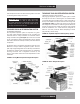
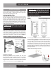
REMOVING GRILL
To remove the grill, loosen, but do not remove, the (4) mounting
screws located on the back side of the grill at the ends. Simply
lift grill up off of its mounting screws and out. To replace the
grill, line up the grill mounting screws with the keyhole slots
located on the cabinet body, push in and down on the grill.
IMPORTANT NOTE: The wiring to the anti-condensate
switch and the thin copper tubing or cable for the ther-
mometer are provided with leads long enough to allow
the grill to be laid across the top of the cabinet after it
has been removed. Take care not to damage the wires or
copper tubing when handling the grill.
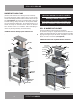
If you need to completely remove the grill from the cabinet,
disconnect the power supply to the cabinet. Remove the wires
on the back of the anti-condensate switch on the grill. Locate the
thermometer sensing bulb and cover, located inside the cabinet.
On Standard Reach-In models, the thermometer bulb cover
is under a small cover channel on the interior top left corner
towards the front of the cabinet. On Designer Line, Pass-Thru,
Roll-In and Roll-Thru models, the thermometer bulb is located
on the interior top, under the air duct. Remove the cover, care-
fully grasp the bulb and push it back through the cabinet hole.
The thermometer bulb and grill can now be removed from the
cabinet. When reinstalling the thermometer bulb, be sure to
replace the sealant putty around the hole into the insulation.
Reattach the leads for the anti-condensate heater switch and
reconnect the cabinet’s power supply.
INITIAL CLEANING PROCEDURE
Prior to start-up and before placing any product inside of your
new model, the interior of the cabinet should be thoroughly
cleaned. Remove the protective film (which is clear on some
models) from all interior sides, bottom and other internal metal
panels, by working the corner loose and slowly pulling the film
back. Washing with a mild soap and warm water solution is
recommended for cleaning the aluminum and stainless steel
surfaces of your cabinet. This should be followed by cleaning
with a baking soda solution (three (3) tablespoons of baking
soda to each quart of warm water). Wipe down thoroughly with
a damp cloth or sponge that has been soaked in clean water and
wrung out thoroughly, and dry with a clean, soft cloth.
IMPORTANT NOTE: Never use harsh detergents, clean-
ers, scouring powders or chemicals when cleaning your
model. Failure to dry the interior surfaces after cleaning
may result in a streaking or staining of the metal.
Complete cleaning procedures and precautions are listed in the
(“Periodic Cleaning Procedure” under “Maintenance”).
START-UP PROCEDURE
ELECTRICAL CONNECTIONS
To insure proper operation, your new model must be connected
to an individual circuit that can supply the full voltage as stated
on the cabinet serial data plate. For correct voltage, power draw,
and wire accommodations, check the data on the serial data
plate located on the inner right wall of your new model. Verify
that this information exactly matches the electrical character-
istics at the installation location. An electrical wiring diagram,
located on the inside compressor compartment rear, next to
the electrical console box, should also be consulted during
connection. For reference, a copy of each electrical wiring dia-
gram is located towards the back of this manual (see “Wiring
Diagrams” section).
Refrigeration compressors are designed to operate within
+/-10% of the rated voltage indicated on the cabinet serial
plate. Excessively high or low supply power can burnout the
compressor. This can be easily detected and will void the fac-
tory warranty. Full voltage at the correct rating, on a separate,
designated circuit, not affected by the operation of other electri-
cal appliances, must be available to the refrigeration unit at all
times. Extension cords should never be used on commercial
equipment, as they can overheat and/or result in low voltage.