
Owners Manual


8
REACH-INS & ROLL-INS
OPERATIONS MANUAL
INSTALLING ROLL-IN AND ROLL-THRU MODELS
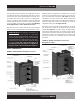
Roll-In and Roll-Thru models are designed to be mounted
directly (without legs or casters) on a flat floor surface in your
building (see Figure 6). The bottom off the cabinet is only about
½” thick, to make it easy to roll carts up and into the storage
area. Roll-Ins and Roll-Thrus must be installed plumb (verti-
cally straight), level (horizontally even) and square for proper
operation of doors and refrigeration system. Proper installation
is similar to Walk-Ins and should only be done by a qualified
technician.
IMPORTANT NOTE: Proper installation and maintenance
is the responsibility of the customer. ANY DAMAGE OR
SERVICE REQUIRED, AS A RESULT OF INCOMPLETE
OR IMPROPER INSTALLATION, WILL NOT BE COVERED
UNDER WARRANTY. FAILURE TO PROPERLY INSTALL
AND LEVEL YOUR EQUIPMENT, INCLUDING, BUT NOT
LIMITED TO, THE INSTRUCTIONS PROVIDED IN THIS
MANUAL. MAY VOID YOUR WARRANTY.
INSTALLING LEGS AND LEVELING
If your new unit is supplied with adjustable legs, they will be
packed in the accessory carton in the cabinet. Your cabinet will
have either four (4) or (6) threaded mounting holes on the bot-
tom of the cabinet (see Figure 5). In order to install the legs,
carefully tip the cabinet back, adding four (4) 2” wood blocks
underneath, and simply screw the threaded leg studs into the
case bottom front leg holes. Repeat this procedure by tilting
the cabinet in the opposite direction and install the remaining
legs. Make sure the legs are tightened extremely well or the
entire model will sway or rock with each opening or closing of
the doors, possibly causing damage to the case bottom. This
procedure should be performed close to the final installation
site and allow access to the rear of the cabinet.
To assure your cabinet is level, all legs are equipped with bullet-
type leveling bolts. These bolts can be turned by hand or by
wrench, clockwise or counterclockwise to level the cabinet.
FIGURE 4A: Casters Must Be Tight to Cabinet Bottom
04/29/10
FIGURE 5: Leg Installation
A
LEG
LEG INSTALLATION
BLOCKS
THREADED
END
TURN FOOT CLOCKWISE
TO REDUCE HEIGHT, OR
COUNTERCLOCKWISE
TO INCREASE HEIGHT.
FIGURE 6: Roll-In and Roll-Thru Installation