
Owners Manual


10
REACH-INS & ROLL-INS
OPERATIONS MANUAL
CONDENSATE REMOVAL (Interior Coil Models)
No floor drains or plumbing connections are required since all
models use an automatic condensate water evaporating sys-
tem. Standard Reach-In models feature an evaporator housing,
located on the inside ceiling of the refrigerated storage area
(see Figure 2) and an electric condensate vaporizer pan with a
mounting bracket packed in the accessory carton.
To install the vaporizer, remove the pan, power cord, cord
clamp and screw from the carton (see Figure 7). Connect the
cord to the vaporizer as shown. Route the cord around the
outside of the pan and through the clamp as illustrated. Secure
the cord and clip to the pan by fastening the mounting screw
into the threaded hole on the side of the vaporizer. Remove the
(2) mounting screws from the back of the cabinet. Position
the bracket as shown and place the vaporizer in the bracket,
making sure the power cord is routed as illustrated. Attach the
bracket to the cabinet with the screws. Using a sharp knife or
scissors, cut the drain tube so the end is about 2” below the
bottom of the cabinet. Place the end of the drain tube in the pan,
making sure the tube is not blocked, kinked, or sitting on the
bottom of the vaporizer pan. Check that the water level switch
is operating correctly by lightly pressing down on the top of the
vaporizer, at the end where the cord is attached. You will hear
a “click” as pressure is applied and another “click” when pres-
sure is removed. If you do not hear the switch “click”, ensure
the vaporizer is seated in the bracket correctly and the cord is
routed correctly and secured in the clamp. Plug the power cord
into the receptacle labeled “VAPORIZER” on top of the cabinet.
IMPORTANT: It is extremely important that the water
level switch operates correctly, that the vaporizer is
plugged into the receptacle labeled “VAPORIZER” and
the compressor is securely plugged into the receptacle
labeled “CONDENSING UNIT”. Improper installation may
cause your cabinet or vaporizer to operate “erratically.”
This can result in water overflowing the pan and onto
the floor.
CONDENSATE REMOVAL(Top Mount Coil Models)
Designer Line Reach-Ins, as well as all Pass-Thrus, Roll-Ins
and Roll-Thrus feature an insulated evaporator housing, located
on the top of the cabinet, out of the food zone (see Figure 2A
& 2B). These models utilize a unique self-contained hot air
evaporating system to automatically eliminate condensate water.
No floor drains or plumbing connections are required and the
system is completely self-contained, so no further assembly
or maintenance is required. In some adverse conditions such
as high ambient temperature, high humidity, extremely heavy
usage, frequent loading for prolonged periods of time, or heavy
pan loading, the amount of condensate water generated could
overflow the pan. If this occurs, the plastic drain tube from the
cabinet can be diverted directly to a floor drain, bypassing the
condensate pan. Alternatively, an optional electric condensate
vaporizer may be purchased as an accessory. An electric con-
densate vaporizer is also supplied with all remote reach-in and
pass-thru models. To install the optional condensate vaporizer,
follow the steps for “Interior Coil Models” in the previous sec-
tion. Remote roll-in and roll-thru models are supplied with an
electric heater in the condensate pan on top of the cabinet, which
must be connected to a power supply by the installer.
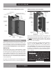
FIGURE 7: Electric Condensate Vaporizer
G
WATER LEVEL
SWITCH
MOUNTING
BRACKET
SCREWS
POWER
CORD
DRAIN
LINE
CLAMP
CORD
CONNECTION
ELECTRIC VAPORIZER WITH WATER LEVEL SWITCH
REACH-IN CABINET
BACK OF
CABINET
FIGURE 8: Reach-In/Roll-In Door Components
HINGE
COVER
MOUNTING
SCREW
ADJUSTMENT
PLATE
HINGE
PIN
HANDLE
SCREW
SCREW COVER
TONGUE
TUMBLER
LOCK HOUSING
GASKET
DOOR
SCREW
KEEPER
BASE
LOCK
KEEPER
REACH-IN/ROLL-IN DOOR COMPONENTS
HALF DOOR SHOWN
(COMPONENTS TYPICAL)