Operation, Installation and Instruction Manual For Undercounter Refrigerators and Freezers and Pizza Preparation Tables A Division of National Refrigeration & Air Conditioning Products, Inc. 539 Dunksferry Road • Bensalem, PA 19020-5908 215-244-1400 • 1-800-523-7138 • Fax: 215-244-9579 www.continentalrefrigerator.
Operators Manual Table of Contents Page Receiving Your New Model ........................................................................................3 General Information And Important Operating Facts ................................................3 Uncrating Your New Model ........................................................................................4 Installation And Location ............................................................................................4 Clearances .........
RECEIVING YOUR NEW MODEL Congratulations on your recent purchase of Continental Refrigerator superior food equipment products! When your shipment arrives, please thoroughly examine the shipping crate for any punctures, dents, or signs of rough handling. It is in your best interest to partially remove or open the shipping container in order to examine the model for any concealed damages which may have occurred during shipment.
UNCRATING YOUR NEW MODEL The shipping container should remain on your model as protection against dents or scratches while transporting it to the actual set-up location. Remove the shipping container only at the last possible moment by following these simple steps: 1. Using a pry bar, pry off and remove crate end bottom staples. 2. Pry off and remove crate front and rear bottom staples. 3. Slide crate upward and remove it, being careful not to rub against cabinet.
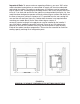
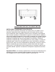
Important Note: To assure maximum operating efficiency, your new “SW” series model should be located where an unrestricted air supply can circulate underneath and behind the cabinet. For optimum performance, the cabinet must be installed on legs or casters (see “installing legs or installing casters” later in this section) and a minimum of 3" on each side and rear of the cabinet must be provided (see figure 1a).
FIGURE 1b MINIMUM CLEARANCE DIMENSIONS WITHOUT LEGS FLOOR LOADS The floor at the final location site must be level, free of vibration and strong enough to support the total combined weights of your new model plus the maximum product load which might be placed into it. A fully loaded reach-in model may reach 2,000 3,000 pounds. To estimate the possible product load weight, assume that each cubic foot of storage space weighs approximately 35 pounds.
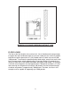
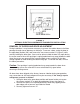
INSTALLING LEGS AND LEVELING Your new “SW” series model is supplied with adjustable type legs for leveling purposes. Each SW27, SW48, SW60 and SW72 model has four leg mounting holes on its case bottom. Legs are packed in the accessory carton from which they must be removed and installed on the cabinet case bottom (see figure 2).
Important Note: It is extremely important that your new model is perfectly level for proper operation. If it is not level, the following adverse conditions will become apparent: 1. The door(s) will not be properly aligned and consequently will not provide a good seal. 2. You model will run excessively due to improper door seal(s). 3. An excessive amount of ice will accumulate inside the cabinet, around the door opening(s) and especially on the finned evaporator coil.
FIGURE 3 CASTERS MUST BE TIGHT TO CABINET BOTTOM INSTALLING CONDENSATE EVAPORATOR No floor drains or plumbing connections are required since all models use an automatic condensate water evaporating system. All models utilize a unique hot air condensate water evaporating system which is completely self-contained and no further assembly or maintenance is required.
FIGURE 4 OPTIONAL ELECTRIC CONDENSATE EVAPORATOR INSTALLATION REMOVAL OF DOORS AND DOOR ADJUSTMENT During installation, it may become necessary to remove the cabinet doors to facilitate passage through narrow doorways or hallways. To remove a door, swing the door to the open-door position (90°) and remove the two screws marked “a” (figure 5) while carefully holding the door open.
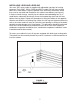
FIGURE 5 DOOR ADJUSTMENT AND REMOVAL SELF-CLOSING HINGE MECHANISM MOUNTING For proper operation of the self-closing doors on all sandwich unit and prep models, the hinge mechanism must be mounted to apply tension in the direction shown in figure 6. When the hinge is moved to the open-door position the hinge should be tensionfree. However, when the hinge is moved back into the closed position, it should snap back.
REMOVAL AND REPLACEMENT OF HINGE MECHANISM To remove the hinge mechanism from the door, remove the door from the cabinet as explained above. As shown in figure 6, remove the hinge plate from the hinge mechanism by removing the hinge pin screw. Also remove the horseshoe spring. Reinstall the hinge pin screw only partially leaving about 1/8" of exposed screw threads. Now, the hinge mechanism mounting screws can be removed thus allowing the mechanism to be removed by pulling on the hinge pin screw.
Important Note: Never use harsh detergents, cleaners, scouring powders or chemicals when cleaning your model. Failure to dry the interior surfaces after cleaning may result in a streaking or staining of the metal. Complete cleaning procedures and precautions are listed in the “periodic cleaning procedure” under the maintenance section.
208-230 VOLT, 60 HZ, 1 PHASE CONNECTION All 208-230 volt models are to be permanently connected and are provided with four (4) field wiring leads which exit the electrical console box located in the machine compartment rear, next to the compressor. The cabinet circuitry is 115 volts and the condensing unit is 208-230 volts in which the wiring includes a neutral and a mechanical ground.
OPERATION All cabinets must be given sufficient time to reach normal operating temperature before placing any food inside cabinet or pans (if equipped). Refrigerators are designed to maintain an ideal cabinet and pan temperature of 38°F to 40°F (3.3°C to 4.4°C) and approximately 1 hour of operation is required to reach this temperature. During pull-down of open top models, pans should be in place and top lid should be kept closed.
PIZZA PREP TEMP ADJUSTMENT - COLDWALL RAIL If an adjustment is necessary to maintain the coldwall rail temperature, a pressure control is located behind the front grill which controls the compressor operation and the temperature range of the rail.
DEFROST OPERATION All freezer models are equipped with an automatic, electric defrost system consisting of an electric evaporator coil heater, evaporator drain pan heater, automatic electric defrost time clock, and defrost high limit switch. The defrost system is time initiated by the time clock and temperature terminated by the high limit switch. The time clock is preset for three (3) defrost periods per day at eight (8) hour intervals and a fail safe cut-off time of 20 minutes.
FIGURE 7 EVAPORATOR ASSEMBLY INTERIOR ACCESSORIES The standard interior accessory package that is supplied from the factory with your new sandwich unit model consists of standard pilaster strips with pilaster clips (four (4)clips per shelf), and one (1) epoxy coated shelf per section. SHELVING INSTALLATION Pilaster strips which support the shelving are secured to the cabinet walls with special pilaster screws which allow the strips to be readily removed for cleaning without the use of tools.
FIGURE 8 STANDARD SHELF PILASTER OPTIONAL ACCESSORIES In addition to the optional heavy-duty pilaster and clip as shown in figure 9, all models are available with an overhead or double-overhead shelf. Models can even be stacked with a heavy duty stacking collar adapter kit as shown in figure 10. Please consult the price list for additional interior and exterior options and accessories available from the factory for your model.
FIGURE 9 OPTIONAL HEAVY-DUTY PILASTER OPTIONAL OVERHEAD OR DOUBLE-OVERHEAD SHELF All open top models are available with an optional overhead or double-overhead shelf. To install either the overhead or the double-overhead shelf, place the shelf into position on the work top (if your model was ordered with the overhead shelf, mounting holes will be added on the cabinet at the factory), line up holes and secure overhead shelf with the supplied screws.
To stack your models, the following instructions should be followed: 1. Decide which model is to be on “top” and which model is to be on “bottom". 2. On “top” model, remove both bottom rear cover screws on “bottom” model, remove both top joggle clip screws with bumpers. 3. Carefully install four legs on “top” model and set this model on the work top of the “bottom” model. (adjust all leg bullets outward (ccw) about three full turns prior to installing) 4.
SAFETY PRECAUTIONS The following safety precautions should be followed when operating any appliances: Always disconnect the power cord before attempting to work on or clean any equipment. Disconnect the power cord when the appliance will be idled for a long period of time. Do not attempt to service this unit yourself as removing any covers may cause exposure to dangerous voltage. Always route the power cord so that it is not likely to be walked on or pinched by other appliances.
Precautions 1. Never use harsh detergents, cleaners, scouring powders, or chemicals when cleaning your model. 2. Strong bleaches tend to corrode many materials and should never come in contact with stainless steel. 3. Tincture of iodine, or iron should not come in contact with stainless steel. These solutions, which cause stainless steel to discolor, should be rinsed off immediately if contact occurs. 4.
MODEL # ____________________________Serial#________________ Notes: ______________________________________________________________ ____________________________________________________________________ ____________________________________________________________________ ____________________________________________________________________ ____________________________________________________________________ ____________________________________________________________________ _____________________________________
TROUBLESHOOTING AND SERVICING GUIDE PROBLEM PROBABLE CAUSE CORRECTION Condensing unit will 1.Line Disconnected, Switch Open. not start - no hum. 2.Fuse Removed Or Blown. 3.Overload Protector Blown. 4.Control “Off” Due To Cold Location. 5.Control Stuck In Open Position. 6.Wiring Improper Or Loose. Condensing unit will not start - hums but trips on overload protector. Condensing unit starts and runs, but short cycles on overload protector. 1.Improperly Wired 2.Low Voltage To Unit. 3.
PROBLEM PROBABLE CAUSE CORRECTION Condensing unit runs, but shorts cycles on: 1.Overload Protector. 2.Thermostat. 3.High Pressure Cut-Out Due To: (a) Insufficient Air Supply (b) Overcharge. (c) Air In System. 4.Low Pressure Cut-Out Due To: (a) Valve Leak. 1.See Problem # 3. 2.Differential Must Be Widened. 3. (a) Check Air Supply To Condenser. (b) Evacuate And Re-charge. (c) Evacuate And Re-charge. 4. (a) Replace, Evacuate And Re-charge. (b) Evacuate And Re-charge. (c) Replace Expansion Device.
PROBLEM PROBABLE CAUSE CORRECTION Product zone temperature too high. 1.Control Setting Too High. 2.Inadequate Air Circulation. 1.Adjust T-Stat. 2.Rearrange Product Load To Improve Air Circulation. 3.Clean Condenser Coil 3.Dirty Condenser Suction line frosted or sweating. 1.Overcharge Of Refrigerant. 2.Evaporator Fan Not Running. 3.Expansion Valve Stuck Open. 4.Expansion Valve Superheat Too Low. Liquid line frosted, cold, or sweating. 1.Restriction In Drier Strainer. 2.
WIRING DIAGRAMS 28
Continental Warranty Procedure Our warranty is 1 year on parts and labor, and 5 years on the compressor from date of original installation on any unit installed after January 1, 1999. Any unit installed before January 1, 1999 has a warranty of 90 days labor, 1 year parts and 5 years on the compressor, from the date of installation. Please consult factory before any warranty service work. We will issue a 4 digit work authorization # to put on the service invoice for payment. Exceptions will be made.
Warranty Compressor Procedures If the compressor fails within the first (12) months of use or (20) months by the date code on the compressor, an “over-the-counter exchange” must be made through a Tecumseh or Copeland dealer. After the first year the additional (4) year compressor warranty is through Continental Refrigeration, and can be handled by one of the following methods: (1)Continental will supply the replacement compressor at no charge and pay for regular ground freight.
Items NOT Covered Under Warranty Consult your owner's manual for detailed information on the following (page #'s listed beside each line item). I. II. III. IV. Preventative Maintenance A. Dirty Condenser (20) B. General Hardware Adjustments 1. Casters/Legs (5-6) 2. Handles 3. Hinges (8-10) 4. Light Bulb Replacement Compressor Failure Due to Poor Air Circulation A. Reach-In, Roll-In Models, Warmers (White)* 1. 12" Above Grill Area (2-3) 2. 3" On Sides, Back & Underneath (Reach-In only) (2-3) B.