
User's Guide


BL28RW-001 OEM Manual and User Guide
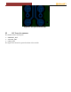
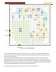
Figure 6-2: NAD Pin Breakout
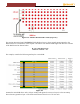
The LTE CAT4 NAD should be oriented on the main board to minimize the length of the PRIMARY_LTE
antenna pin (LTE Ant1). This 50ohm line should be as short as possible to the external RF connector or
internal antenna feed point.
The RF traces from the NAD antenna pins on the main board can be stripline or microstrip. For the
stripline approach, vias should be placed to the NAD EDGE SIDE of the pins as close as possible to the
NAD antenna pads to minimize any impedance discontinuity (see figure 38). For the microstrip approach,
the PCB insertion loss will be less but the short route under the NAD MUST BE TREATED AS STRIPLINE SO
IT WILL BE NARROWER UNDER THE NAD THAN THE MICROSTRIP LINE.
The NAD has ground cleared out under the RF antenna routes as shown below: