
User's Guide


• GNSS_ANT_1
• GNSS_ANT_2
• CV2X_ANT_1
• CV2X_ANT_2
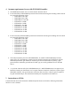
Multi-transmission is not possible. The figure below shows the general breakout of the module:
Figure 2: NAD Pin Breakout
The FE4NA0210 NAD should be oriented on the main board to minimize the length of the primary LTE
TX/RX antenna (LTE_ANT_1). This 50ohm line should be as short as possible to the external RF
connector or internal antenna feed point.
The RF traces from the NAD antenna pins on the main board can be stripline or microstrip.
For routing microstrip lines UNDERNEATH the NAD on layer 1, these ground cutouts internal to the
NAD need to be accounted for in the stripline calculation. The internal GND height and dielectric
constant of the NAD board are shown below:
H = 19.3 mils (491 micron)
Dielectric Constant = 4.1