
Owner manual


5 - 95
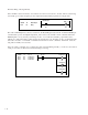
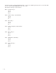
The reset inputs (act as coils) are labelled:
Lch1 Rst (PLC Bit 120)
Lch2 Rst (PLC Bit 121)
Lch3 Rst (PLC Bit 122)
Lch4 Rst (PLC Bit 123)
The outputs (used as contacts or status) are labelled:
Lch1 Out (PLC Bit 16)
Lch2 Out (PLC Bit 17)
Lch3 Out (PLC Bit 18)
Lch4 Out (PLC Bit 19)
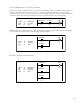
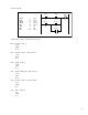
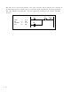
A latch can be used to reverse the direction of motion with two sensors, one for forward, one for reverse. The
sensors will only be active temporarily, so the latch retains the state until the opposite sensor is reached. The
forward sensor is connected to DI_10, the reverse input to DI_11.
LOAD 10 DI_10
OUT 120 Lch1 Rst
DI_10
10
Lch1 Rst
120
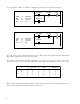
LOAD 11 D_11
OUT 116 Lch1 Set
DI_11
11
Lch1 Set
116
LOAD 16 Lch1 Out
OUT 159 Negate LS
Lch1 Out
16
Negate LS
159
(forward)
(reverse)
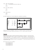
The Latch set and reset rungs should be placed next to each other. The output of the Latch is set at the
conclusion of the scan.
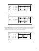
You can create your own custom latch using standard PLC logic.
DI_8
8
Tmp1
108
Tmp1
108
DI_9
9
8 DI_8
108 Tmp1
9 DI_9
108 Tmp1
LOAD
OR
AND NOT
OUT