
Owner manual


6 - 14
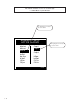
STD SIGNAL MONITOR / LEAD P1/3
The STD Signal Monitor / Lead screen (page 1) displays parameters that are related to the Frequency Input 1
signal.
Cntrl Loop
Control Loop (MP-49) displays the present operating mode of the CX-1200. Only one type of loop can be active at a
time. These modes are automatically selected depending on the present system State (MP-50).
3 = Psn Hld (H-Stop Position Loop)
2 = Position Loop
1 = Velocity Loop
0 = Open Loop
State
State (MP-50) displays the present system operating state of the CX-1200 (see list below). Only one operating state
may be active at a time. To access either the “Run” or the “Jog” operating state, the F-Stop, R-Stop and H-Stop inputs
must be closed.
9 = Not Defined 8 = Diagnostics 7 = Not Defined
6 = Not Defined 5 = Jog 4 = Not Defined
3 = Run 2 = H-Stop 1 = R-Stop
0 = F-Stop
FI1 Hz
Frequency Input 1 Hertz (MP-01) displays the current frequency of the Frequency Input 1, in Hertz.
FI1 RPM
Frequency Input 1 RPM (MP-02) displays the current speed of the Frequency Input 1 encoder in RPM, based on PPR
FI1 (CP-261).
Ld EU/Tm
Frequency Input 1 Engineering Units per Time (MP-05) displays the current speed of the Frequency Input 1 in the
Engineering Units per Time (EU/Tm) relative to the Pulses FI1 (CP-262), EU FI1 (CP-263) and Time Base (CP-209). The
placement of the decimal point is the same as the placement of the decimal point in EU FI1 (CP-263).
Ld Posn
Lead Position (MP-10) displays the present value of the Lead Position in Engineering Units, as specified by Pulses FI1
(CP-262) and EU FI1 (CP-263). The placement of the decimal point is the same as the placement of the decimal point in
EU FI1 (CP-263).
PosnErr
Position Error (MP-33) displays the value, in engineering units, of the accumulated position error between the lead
(FI1) and the feedback (FI2) input signals. The placement of the decimal point is the same as the placement of the
decimal point in EU FI2 (CP-268).