
Owner manual


6 - 23
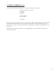
CONTROL OVERRIDES / STATE P1/4
The Control Overrides / State screen (page 1) allows you to select and monitor the operating state for the
CX-1200. The first line on the screen displays the current operating state.
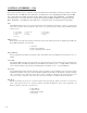
State
State (MP-50) displays the present system operating state of the CX-1200 (see list below). Only one operating state
may be active at a time. To access either the “Run” or the “Jog” operating state, the F-Stop, R-Stop and H-Stop inputs
must be closed.
9 = Not Defined 8 = Diagnostics 7 = Not Defined
6 = Not Defined 5 = Jog 4 = Not Defined
3 = Run 2 = H-Stop 1 = R-Stop
0 = F-Stop
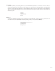
Run Mode
Run Mode (CP-202) sets the mode of operation and the subsequent Setpoint, that are used when your system is in
“Run”. The Setpoint and mode of operation combined, determine the Reference Speed and, if applicable, the
Reference Position. The modes of operation are:
4 = Inv Foll Mode
3 = Follower Mode
2 = Master Mode (default)
1 = Direct Mode
Blk Sel Source
Block Select Source (CP-478) determines whether the active block will be selected by the digital inputs and PLC, by
Keypad Blk Sel (CP-479) or by Cntr4 Cnt.
3 = Cntr4 Cnt
2 = KyPd = Keypad Blk Sel
1 = DgIn = Digital Inputs/PLC (default)
Keypad Blk Sel
The Keypad Block Select (CP-479) determines which block will be active when Blk Sel Source (CP-478) is set to “2”
(KyPd).
Active Blk
Active Block (MP-51) displays the active block (0-7). The block can be selected and made active by the Block select
bits (Blk Sel A,B.C), in the PLC Programming screen if Blk Sel Source (CP-478) is set to “1” (DigIn & PLC). Or the block
can be selected and made active by the keypad if Blk Sel Source (CP-478) is set to “2” (Keypad Blk Sel).
Cntrl Loop
Control Loop (MP-49) displays the present operating mode of the CX-1200. Only one type of loop can be active at a
time. These modes are automatically selected depending on the present system State (MP-50).
3 = Psn Hld (H-Stop Position Loop)
2 = Position Loop
1 = Velocity Loop
0 = Open Loop