
Datasheet

data sheet
Induktiver Näherungsschalter
Détecteur de proximité inductif
Inductive Proximity Switch
Durchmesser Schaltabstand Einbau
Diamètre Portée Montage
Diameter Operating distance Mounting
CONTRINEX AG Industrial Electronics
route André Piller 50 - CH 1762 Givisiez - Switzerland - Tel: ++41 26 460 46 46 - Fax: ++41 26 460 46 40 - Internet: www.contrinex.ch - E-mail: headoffice@contrinex.ch
DW - A - 509 - M12 - 3 0
M12
0...6 mm
quasi-bündig
quasi-noyable
quasi -embeddable
Ausführung mit Analogausgang
Wichtigste Eigenschaften:
- Erfassungsbereich 0 ... 6 mm
- Betriebsspannung 15...30 VDC
- Spannungsausgang 0 ... 10 V
- Stromausgang 4 ... 20 mA*
- Kurzschlussschutz, Induktions-
schutz, Verpolungsschutz eingebaut
- Nicht linearisierte Ausführung
- Anschluss über Kabel oder Stecker
S12
* nur DW-A#-509-M12-390
Appareil à sortie analogique
Caractéristiques principales:
- Domaine de détection 0 à 6 mm
- Tension de service 15 ... 30 VDC
- Tension de sortie 0 à 10 V
- Courant de sortie 4 à 20 mA*
- Protections contre les courts-circuits,
les surtensions induites et l'inversion
de tension incorporées
- Version non linéarisée
- Raccordement par câble ou par
connecteur S12
* seulement DW-A#-509-M12-390
Device with analog output
Main features:
- Sensing range 0 to 6 mm
- Supply voltage 15 ... 30 VDC
- Output voltage 0 to 10 V
- Output current 4 to 20 mA*
- Protections against short-circuits,
induced overvoltages and voltage
reversal built-in
- Non-linearized version
- Cable and S12 connector versions
* only DW-A#-509-M12-390
Technische Daten:
(gemäss IEC 60947-5-2)
Erfassungsbereich s
d
Normmessplatte
Wiederholgenauigkeit (gemäss IEC
60947-5-2)
Wiederholgenauigkeit (T
A
= konstant)
Auflösung
Betriebsspannungsbereich U
B
Zulässige Restwelligkeit
Ausgangsspannung an A1 s = 0 mm
(Fig. 1) s = 3 mm
s = 6 mm
Laststrom am Spannungsausgang A1
Ausgangsstrom an A2 * s = 0 mm
(Fig.1) s = 6 mm
Max. Last am Stromausgang A2 *
Leerlaufstrom
Bandbreite
Bereitschaftsverzögerung
Umgebungstemperaturbereich T
A
:
A1 belastet, A2 unbelastet
A1 unbelastet, A2 belastet
Temperaturdrift von s
r
Kurzschlussschutz
Verpolungsschutz
Schocks und Schwingungen
Leitungslänge
Gewicht (Kabel / Stecker)
Schutzart
EMV - Schutz:
IEC 60255-5
IEC 61000-4-2
IEC 61000-4-3
IEC 61000-4-4
Gehäusematerial
Aktive Fläche
Anschlusskabel (andere Längen auf
Anfrage)
Caractéristiques techniques:
(selon CEI 60947-5-2)
Domaine de détection s
d
Cible normalisée
Reproductibilité (selon CEI
60947-5-2)
Reproductibilité (T
A
= constant)
Résolution
Tension de service U
B
Ondulation admissible
Tension de sortie à A1 s = 0 mm
(Fig. 1) s = 3 mm
s = 6 mm
Charge à la sortie tension A1
Courant de sortie à A2 * s = 0 mm
(Fig.1) s = 6 mm
Charge max. à la sortie courant A2 *
Courant hors-charge
Bande passante
Retard à la disponibilité
Plage de température ambiante T
A
:
A1 chargé, sans charge sur A2
sans charge sur A1, A2 chargé
Dérive en température de s
r
Protection contre les courts-circuits
Protection contre les inversions
Chocs et vibrations
Longueur du câble
Poids (câble / connecteur)
Classe de protection
Protection CEM:
CEI 60255-5
CEI 61000-4-2
CEI 61000-4-3
CEI 61000-4-4
Matériel du boîtier
Face sensible
Câble de raccordement (autres
longueurs sur demande)
Technical data:
(according to IEC 60947-5-2)
Sensing range s
d
Standard target
Repeat accuracy (according to IEC
60947-5-2)
Repeat accuracy (T
A
= constant)
Resolution
Supply voltage range U
B
Max. ripple content
Output voltage at A1 s = 0 mm
(Fig. 1) s = 3 mm
s = 6 mm
Load at voltage output A1
Output current at A2 * s = 0 mm
(Fig.1) s = 6 mm
Max. load at current output A2 *
No-load supply current
Bandwidth
Time delay before availability
Ambient temperature range T
A
:
load at A1, no load at A2
no load at A1, load at A2
Temperature drift of s
r
Short-circuit protection
Voltage reversal protection
Shocks and vibration
Cable length
Weight (cable / connector)
Degree of protection
EMC protection:
IEC 60255-5
IEC 61000-4-2
IEC 61000-4-3
IEC 61000-4-4
Housing material
Sensing face
Connection cable (other lengths on
request)
0 ... 6 mm
18 x 18 x 1 mm
0,3 mm (U
B
= 20 ... 30 VDC,
T
A
= 23
o
C ± 5
o
C)
± 0,01 mm
≤ 1 µm
15 ... 30 VDC
≤ 20% U
B
0 V / - 0 + 0,4 V (23
o
C)
+ 5,2 V / ± 0,4 V (23
o
C)
+ 10 V / ± 0,4 V (23
o
C)
≤ 10 mA
4 mA / ± 0,8 mA (23
o
C)
20 mA / ± 0,8 mA (23
o
C)
0,5 kΩ (U
B
= 15V) / 1kΩ (U
B
= 30V)
≤ 12 mA
1 kHz (-3 dB bei / à / at s = 3 mm)
≤ 50 msec
-25 ... +70
o
C
gemäss / selon / acc. to Fig. 2
≤ ±5% (0 ... +70
o
C)
≤ ±10% (-25 ... 0
o
C)
eingebaut / intégrée / built-in
eingebaut / intégrée / built-in
IEC 60947-5-2 / 7.4
300 m max.
-390: 95 / 33 g; -320: 90 / 30 g)
IP 67
5 kV
Level 2
Level 3
Level 2
Messing cr/laiton cr/cr-plated brass
PBTP
PUR 4 x 0,25mm
2
/ 128 x 0,05mm Ø
2 m
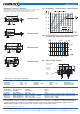
Anschlussschemas / Schémas de raccordement / Wiring diagrams Steckerbelegung (Gerät)
Attribution des pins (appareil)
Pin assignment (device)
-390 -320
S12