Disclaimer Control4® makes no representations or warranties with respect to this publication, and specifically disclaims any express or implied warranties of merchantability or fitness for any particular purpose. Control4 reserves the right to make changes to any and all parts of this publication at any time, without any obligation to notify any person or entity of such changes. Trademarks Control4, EZ ID, and the Control4 logo are trademarks or registered trademarks of Control4 Corporation.
Contents Preface Important Information .................................... 1 Graphical Symbols in this Guide............ 1 Graphical Symbols on the Device.......... 1 Safety Instructions ................................. 2 Additional Resources ............................. 3 Chapter 1 Introduction to Multi Channel Amplifier - 16... 5 Features and Benefits............................ 5 Requirements ........................................ 6 What’s in the Box ...................................
FCC Interference Statement........... 23 Industry Canada Statement ............ 23 Recycling Information ..................... 24 Warranty ......................................... 24 Index .....................................................................................
PREFACE Important Information Graphical Symbols in this Guide Warning, Important, and Note paragraphs draw your attention to important safe practices and additional information which may help you avoid injury, death, or loss of material or time. WARNING! This indicates a potentially hazardous situation that, if not avoided, may result in death or serious injury.
Safety Instructions 1. Read these instructions. 2. Keep these instructions. 3. Heed all warnings. 4. Follow all instructions. 5. Do not use this apparatus near water. 6. Clean only with dry cloth. 7. Do not block any ventilation openings. Install in accordance with the manufacturer’s instructions. 8. Do not install near any heat sources such as radiators, heat registers, stoves, or other apparatus (including other amplifiers) that produce heat. 9.
have fallen into the apparatus, the apparatus has been exposed to rain or moisture, does not operate normally, or has been dropped. 15. Do not install in a cabinet that is smaller than 20” wide x 20” deep x 12” high. WARNING! Do not expose the apparatus to dripping or splashing. Do not place objects filled with liquids near the apparatus. WARNING! To reduce the risk of fire or electrical shock, do not expose this apparatus to rain or moisture.
4
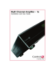
CHAPTER 1 Introduction to Multi Channel Amplifier - 16 Control4 systems are uniquely configured for every customer and every site. A popular component among music lovers is the Control4 Multi Channel Amplifier. This chapter introduces the Control4 Multi Channel Amplifier - 16 and its features. Features and Benefits Receives up to eight stereo inputs with full audio switching on inputs.
Requirements Ensure that your home network wiring is in place before starting your system setup. The Multi Channel Amplifier can be controlled through Ethernet or through ZigBee mesh networking (IEEE 802.15.4). Device must not be installed in a cabinet that is smaller than 20” wide x 20” deep x 12” high. What’s in the Box The following hardware and software is required and included in your Control4 Multi Channel Amplifier box.
routing and zone settings for gain, bass, and treble. The display also shows zone activity. 2. Buttons—Provides access to menu options displayed on the LCD. 3. Select Dial—Rotate to scroll through list items and options displayed on the LCD. Press to make selections. Back View 1 2 3 4 1. Power Plug Port—For use with a standard IEC equipment power cord. Use the supplied power cord or ensure the power cord you are using is at least 18 AWG or larger. 2.
Technical Specifications Multi Channel Amplifier - 16 Table 1: Multi Channel Amplifier - 16 C4-16AMP3-B Multi Channel Amplifier - 16 Communications: Ethernet 10/100 base and Zigbee mesh networking Connections: 8 sets of stereo inputs 8 sets of amplifier outputs Dimensions: 5.
CHAPTER 2 Installing the Multi Channel Amplifier This device operates as part of the Control4 home system, which requires physical connections and logical connections to function as designed. The essential setup tasks are: 1.Plan Your Physical Layout 2.Connect Audio Input Sources and Speakers 3.Connect to the Network and Power 4.Set Up Logical Connections 5.
Plan Your Physical Layout This section can help you plan your physical connections. Use a worksheet to plan your amplifier connections: Using the worksheet provided in Table 2-1 below, identify the connection you will use for all planned connections. 10 Output examples: Speakers 8 stereo channel outputs Amplifier Outputs— Input examples: CD changers, VCRs, TVs, DVD changers, or Media Controllers Audio Inputs— 8 stereo sources 1 A1B 2 A2B 3 A3B 4 A4B 5 A5B 6 A6B 7 A7B 8 A8B Table 2-1.
WARNING! Connecting speaker wires or input cables while the Multi Channel Amplifier is powered, may cause shock and could damage the amplifier. Connect Audio Input Sources and Speakers 1. Ensure the amplifier power cord is unplugged before connecting speakers and audio sources. 2. Connect up to eight stereo audio source devices to the RCA line level input jacks (the top row of connector on the back of your amp).
Connect to the Network and Power 1. If you are using an Ethernet connection for the Multi Channel Amplifier, use a standard 10/100 Base T Ethernet cable to connect the Ethernet port on the amplifier to your network. NOTE: While the Multi Channel Amplifier can be controlled via either Zigbee or Ethernet networks, Control4 recommends that you use an Ethernet connection whenever possible as this will allow firmware upgrades to be performed on the product.
Set Network Settings 1. At the LCD screen, press the Network button. 2. On the Network Configuration screen, choose an Ethernet or ZigBee network by rotating and pressing the Select Dial. 3. If the amplifier is set to use a ZigBee network, the EUID, Gateway, and ZigBee channel number are displayed. The EUID and Gateway are static fields. The Zigbee channel number can be changed. Press the Select Dial to enter edit mode. Rotate the dial or use the Up or Down button to change the channel number.
4c. Press OK (or press the Select Dial). 4d. Press Save (or press the Select Dial). 4e. Edit the IP, Mask, and GWay fields for the Static IP network: Use the Select Dial to select a line, then press the dial. Use the Select Dial scroll the number up or down and edit as needed, then press the Select Dial to move to the next field within the number. 4f. When finished editing, press Save.
CHAPTER 3 Using Multi Channel Amplifier This chapter introduces the LCD user interface screens on the Multi Channel Amplifier and the common system tasks you can perform. Normal day-to-day tasks do not require manual control but instead are controlled using the Control4 user interface. View Output Assignments Once you complete the physical connections and logical connections (using the Composer software as needed), you can view or change your setup in the Multi Channel Amplifier front display.
zones and any assigned input sources (such as Input 1 as shown in the following screen). A shaded arrowhead indicates that a signal is present. The menu buttons on the front panel provide access to the following screen: Setup: Displays an output-specific screen, such as Output Zone 1. Network: Displays the Network Configuration screen. Display: Displays the Display Configuration Screen.
Manage Amplifier Output Zones View or Change Output Settings To view or change source settings: 1. On the In to Out Assignments screen, press the Setup button. The output settings of the default output screen (the last output screen accessed) are displayed. In the following example it is Output Zone 1. You can choose to view the settings for a different output screen by changing the output number (see Step 2).
Menu buttons: Provide access to these screens: Inputs: Toggles view to a screen showing the gain for the currently assigned input. Tone: Displays the bass gain, bass frequency, treble gain, and treble frequency for this output. Exit: Returns to the In to Out Assignments screen. 2. (Conditional) View a different output number: If the output screen that you want to view is not displayed, use the Select Dial to select and change the output number at the top. 3. (Optional) Change an output setting: 3a.
If you choose to edit the Treb Freq field, a new menu is displayed at the bottom of the screen, which includes the options Down, Up, OK, and Cancel. You can use these menu options to change this setting or continue using the Select Dial as you have previously done. 4c. Press the Select Dial to enter Edit mode. 4d. Rotate the dial to change the setting. Press the dial to save the new setting and exit the Edit mode. To exit without saving, use the front panel button indicated to choose Cancel. 4e.
4. (Optional) Press the Outputs button to toggle back to the last Output screen that was accessed. 5. Press the Exit button to return to the In to Out Assignments screen. View Network Settings 1. On the In to Out Assignments screen, press Network. To display the network settings, select Ethernet or Zigbee (depending on which the amp uses). 2. To edit these settings, see Set Network Settings on page 13. 3. Press the Back button to return to the In to Out Assignments screen.
2. Use the buttons or the Select Dial to choose a setting to change: Once you press the Select button (or press the dial), you enter Edit mode. 3. In Edit mode, use the buttons or Select Dial to change the highlighted setting. Press the OK button (or press the dial) to save the change and exit Edit mode. Brightness: Supported range: 0 to 100 Contrast: Supported range: 0 to 100 Backlight Timeout: Supported settings are Off (always off) 1 to 90 seconds (default is 10 seconds) On (always on) 4.
22
CHAPTER 4 Regulatory Compliance This product complies with the standards and practices referenced in this section for North America, Europe, or Australia/New Zealand. North America FCC Interference Statement This device complies with Part 15 of the FCC Rules. Operation is subject to the following two conditions: (1) This device may not cause harmful interference, and (2) this device must accept any interference received, including interference that may cause undesired operation.
Recycling Information For information on recycling, please go to www.control4.com/ recycling Warranty This device has a limited two (2) year warranty on parts from the date of purchase. Control4 will replace or repair any defective unit. Return unit to the place of purchase for replacement. For any damages incurred, the warranty will never exceed the purchase price of the device. This warranty does not cover installation, removal, or reinstallation cost.
Index Numerics 5-Band Parametric Equalizer 21 A Additional Resources 3 Amplifier Outputs 7 Audio Input Connect Audio Input Sources and Speakers 11 Audio Inputs 7 Change Settings 19 Connect Audio Input Sources and Speakers 11 View Settings 19 B Backlight Timer 21 Balance 17 Bass Freq 18 Bass Gain 18 Brightness 21 Buttons 7 C Connections Connect Power 12 Connect to Power 12 Connect to the Network 12 Logical Connections 12 Contrast 21 25
D Display Set Preferences 20 Settings Backlight Timer 21 Brightness 21 Contrast 21 Display Button 16 E Ethernet 13 DHCP 13 Static IP 13 Ethernet Port 7 F Features and Benefits 5 Front Display 6 G Gain 17 I Importants 1 In to Out Assignments Screen Menu Buttons 16 Input 17 Installation Connect Audio Input Sources and Speakers 11 Connect to the Network and Power 12 Logical Connections 12 Network Settings 13 Physical Layout 10 26
L Limit 17 M Menu Buttons (Assignments Screen) 16 Display 16 Network 16 Setup 16 Menu Buttons (Output Screen) 18 Inputs 18 Tone 18 Menu Buttons (Output) Tone 18 Menu Buttons (Tone) Exit 19 Outputs 19 Multi Channel Amplifier 6 Amplifier Outputs 7 Audio Inputs 7 Back View 7 Buttons 7 Connection Worksheet 10 Ethernet Port 7 Front Display 6 Front View 6 Power Plug Port 7 Select Dial 7 Multi Channel Amplifier Connection Worksheet 10 N Network Connect to the Network 12 Ethernet 13 Settings 13 View Settings 20 Z
Network Button 16 Notes 1 O Options Available in Composer 21 5-Band Parametric Equalizer 21 Volume Curve 21 Output Change Settings 17 Menu Buttons 18 Inputs 18 Tone 18 Settings Balance 17 Gain 17 Input 17 Limit 17 View Output Assignments 15 View Settings 17 P Power Plug Port 7 R Recycling Information 24 Regulatory Compliance 23 Requirements 6 S Safety Instructions 2 Select Dial 7 Setup Button 16 Speakers Connect Audio Input Sources and Speakers 11 Static IP 13 System Status Screen 15 28
T Tone Menu Buttons Exit 19 Outputs 19 Settings 18 Bass Freq 18 Bass Gain 18 Treb Gain 18 Treb Gain 18 V Volume Curve 21 Volume Limit 17 W Warnings 1 Warranty 24 What’s in the Box 6 Z Zigbee 13 29
30