
User guide

Composer Pro User Guide
Copyright © 2012 Control4. All Rights Reserved.
Saved: 1/20/2012 1:31:00 PM
200-00005 Composer Pro
User Guide Part 1
Page 140 of 199
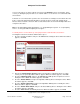
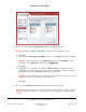
9. You have just completed defining audio/video connections. Click next to continue to the next
section to define Control connections.
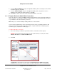
2.9.1.5 Example: Define the Control Connections
This section discusses using Control4® Interviewer wizard in Composer Pro to define the Control
connections.
Note: This process follows “Example: Define the Audio/Video Connections.”
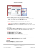
You are now in the Control section of Interviewer. In this section, you identify all Control connections
in the system.
Tip: To complete this section, refer to the control connection tables shown in the "Hardware
Connections" section "From Output to Input" in “Example: System Specifications.”
Using the Smith Home example project (a Controller project), complete the following steps.
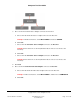
To define Control connections:
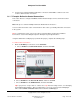
1. Define the IR OUT port connections on the Controller.
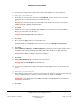
a. Choose IR OUT 1 to Television IR Sensor, and then click next.
b. Choose IR OUT 2 for the Receiver IR Sensor, and then click next.
c. Choose IR OUT 3 for the DVD IR Sensor, and then click next.
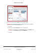
Tip: If you prefer to set up a video or contact sense loop instead of using a macro, see “Changing
Power Management Options.” After you add a video sense loop connection to the DVD player
driver, add a control connection between the Controller and DVD player.