
User guide


Composer Pro User Guide
Copyright © 2012 Control4. All Rights Reserved.
Saved: 1/20/2012 1:31:00 PM
200-00005 Composer Pro
User Guide Part 1
Page 65 of 199
To add and configure a Wireless Outlet Dimmer:
Note: Each Wireless Outlet Dimmer has two (2) outlets: Outlet 1 and Outlet 2. When the Wireless
Outlet Dimmer is plugged into a wall, Outlet 1 is on the left and Outlet 2 is on the right.
1. Start Composer and connect to a Director.
2. Click System Design.
3. In the Items pane > My Drivers tab > Lighting > Light double-click the Wireless Outlet Dimmer
object driver to add to the project.
4. Double-click the Outlet Light twice to add one for each outlet.
5. Ensure that three (3) objects are added to the project tree:
• One (1) for the Wireless Outlet Dimmer
• Two (2) other objects representing Outlet 1 and Outlet 2 (Light 1 and Light 2)
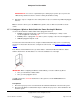
6. In the Connections view, use the Network tab to make the necessary network connection. To do
this, select the Wireless Outlet Dimmer object, and click the Identify button.
7. In Identify mode, go to the physical Wireless Outlet Dimmer and press the Button four (4) times
to identify the device to the network. The address appears in the box.
8. Click Close to exit the wizard.
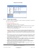
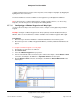
9. To configure the properties, click System Design. In the project tree, select the Wireless Outlet
Dimmer object to view the device properties.
• LEDs—Enabled/Disabled radio buttons—Lets you enable or disable the LED lights on the
Wireless Outlet Dimmer.
• Networking
Channel—Lets you view the channel that the device is using to communicate on the
network.
Gateway —Lets you view the Gateway that the Wireless Outlet Dimmer is using on the
network.
MAC—Lets you view the MAC address that the Wireless Outlet Dimmer is using on the
network.
Version—Lets you view the Wireless Outlet Dimmer version.
2.5.7.8 Configuring Lights for 3-Way
Rather than creating programming to tie lighting variables and Control4
®
3-way lights together, you
can use a simplified lighting configuration to set up lighting control. In the Connections view, you can