
User guide

Composer Pro User Guide
Copyright © 2012 Control4. All Rights Reserved.
Saved: 1/20/2012 1:31:00 PM
200-00005 Composer Pro
User Guide Part 1
Page 71 of 199
• Contact Open—The LED is on when the auxiliary contact is in the Open position.
• Contact Closed—The LED is on when the auxiliary contact is in the Closed position.
• Unmanaged—The LED is not tied to the contact or load and can be controlled using the
Programming view.
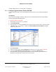
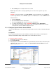
Virtual Button Colors
The virtual button color defines the LED color that will appear on a keypad button that is bound to
the Puck module when that keypad button is set to Follow Bound Color.
Select a virtual button LED from the drop-down list, choose the LED color and then click the Set
button. (Note: the Set button must be clicked before selecting a different virtual button LED from
the drop-down list or the previous selection will be lost.)
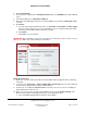
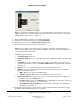
Fault Detection
The status field indicates whether the Puck Module is in a fault state. Fault conditions can be
caused by a short circuit, overloading the module, or potentially an incandescent bulb blowing.
To reset the device, click the Reset button. Alternatively, the button on the Puck or the button
attached to Contact 1 can be clicked 15 times to reset the device.
If the device returns to a fault state after reset, verify the wiring and and/or the total wattage of
loads connected to the device.
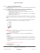
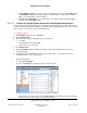
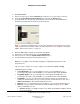
Load Profile (Wireless Puck Dimmer Module Only)
These are the minimum and maximum load settings for light output which includes the Cold Start
Level and time. Test the settings to determine what fits best with your bulb type.
Note: The Navigators show 0% to 100% even though the settings may be set at Minimum On
Level percent at 25%, and the Max On Level percent at 80%.
Minimum On Level (%)—Use the arrows selection box to select the minimum % in 1%
increments. The default is 0. The minimum level can vary, depending on the light type
(incandescent, fluorescent, LED, etc.).
This is especially important in compact fluorescent (CLF) and LED lighting that sometimes have a
minimum threshold for producing visible light that could be anywhere from the 10 – 40% range.
Some loads will flicker or pulse right at their minimum threshold.
Example: A bulb doesn’t produce visible light until it reaches 20%. The minimum On to 25% will
ensure a clean On transition.
Cold Start Level (%)—Use the arrows selection box to select the start level in 1% increments.
The default is 0. This level is set above the Minimum on level % setting.
This setting is mainly applicable to CFL loads. Switching from an Off state to On sometimes
exhibits a higher visible light threshold than after the CFLs have been on and have warmed up. If
a Cold Start % is set (above the Minimum On %), the Dimmer cleanly jumps to that level from Off
to On. However, when the Dimmer has been on for the time period designated by the Cold Start
timer, the Dimmer can ramp below the Cold Start On % to the minimum On%.