AR E:C • INC • • TECMAR, INC.
--.--.. . ' ·.. . 1~ ...... ~. 1,· .... J:.' - ~. . •• ., . ,. "1" , ' .
~ INC. TECMAR, INC. • 23600 Mercantile Road • Cleveland, Ohio 44122 • TM-AD212 5-100 Analog to Digital Converter and Timer/Counter Board Copyright 1980 Teemar, Inc.
~ INC. TECMAR, INC. • 23600 Mercanlile Road • Cleveland, Ohio 44122 • Phone; (216) 464-7410 ERRATA It is possible that the AD212 board will po,.er up with the AD DONE flag set (:1), If your program uses this flag either for interrupts or status checking, it will be necess!ry to clear the flag when initializing the board. This can be done simoly by reading the high AID byte which automatically resets the AD DONE fl ag. Pins 20,53, and 70 have been connected to ground per IEEE standard.
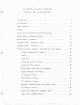
T E C MAR S TAB L E OF 100 A0 2 1 2 CON TEN T S Introduction. 1 AID Features 3 Timer Features 4 Options . . . • AD212 Circuit Description and Set-up Guide , 5 6 Mother Board Component layout 17 Mother Board Schematic . . . . 18 Daughter Board Component layout 19 Daughter Board Schematic . . . . 20 Switch and Jumper Summary - Organized bv Switch Number. 21 Switches Organized by Function 24 Jumoers.
Jumpering for MP6912 Module. 39 Jumpering for OT5701 Modules 40 Jumoering for OT5712 and OT5702 Modules 41 Jumpering for OT5703 Modules . . . . . 42 Two's Complement From a 12 Bit Module 43 Binary or Offset Binary From a 12 Bit Module 44 Jumpering for OT5714 Module.. 45 . ..... Nonnal Data Conversions for a 14 Bit Module 46 Converting a Two's Complement to Offset Binary for 14 Bit Module. . .... 47 Jumpering for OT5716 Module 48 Normal Data Conversions for a 16 Bit Module.
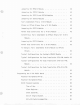
Timer Control of A/D. . . . 66 AD212 Assembly language Examoles. 68 Time of Day . . 68 Alarm Reg;ster. 73 Event Counti ng. 74 A/D of Single Channel 75 A/D with Auto-Incrementing. 77 Aoplication Note 1:0oeration of the AD231 Expander boards in Free-Run Mode. 79 Appendix A--Amg513 Specifications A-l Aopendix B--Inout Range Parameters (Resistor and Capacitor Values needed with Programmable Gain Dotion) . . . . . . . . . . . B-1 .A.ppendix C--Cabling Between Mother and Daughter Board. . . .
I NTROOUCT ION The Tecmar 5-100 AD212 board is designed for sophisticated industrial, scientific. corrmercial. laboratory or educational apolications requiring high-speed, accurate analog to digital conversion including real time aoolications. The AD212 interfaces various Complete Data Acquisition Modules and the A~D 9513 Timer Controller to each other and to the 5-100 bus.
2 The AID can be triggered by an external device. A TTL compatible signal is required. The external tr;gqer signal ;s under software control. For example. the board could respond to CPU commands which would mask out the external trigger, i.e., the AID could not respond to the external triggers, and at a later time. under software control, the board could be made to trigger on an external signal.
3 A02l2 FEATURES IEEE 5-100 16 single-ended or 8 true differential inputs jumper selectable 12 bit accuracy and resolution standard 30 KHz conversion rate standard I/O or memory maDped -- switch selectable Jumper selectable input ranges: ±lOV. ±5V, 0 to +lQV. 0 to +5V Output formats: two's complement.
4 TIMER FEATURES In addition to the AID features, the AD212 contains a Dowerful timer circuit which can start AID conversion and can also be used independently for time of day. event counting. frequency shift keying and many other applications.
5 A02l2 OPTIONS Prograrrmable 9ai n up to 1000 14 bit accuracy 16 bit accuracy 40 KHz conversion rate 100 KHz conversion rate 125 KHz conversion rate Screw terminal and signal conditioning panel with optional thermocouple cold junction comoensation and rack mount enclosure Enclosure and cable for remote daughter board Low level, wide range (10mV to 10V FSR) permitting low level sensors such as thermocouples.
6 AD,1, CIRCUIT ,. ~,SCRIPTIO~ AND SET-UP GUIDE Conventions • Orientation references in the fol1owin3 description such as I'U,. dOk'n". etc. assu,e tnat the ADZ12 is being viewed with its S100 connector (Pl) oointing down. Signals described as being "high" or "low" refer to voltages of 3 to 5 volts or zero volts. resoectively.
7 3. Address Decoding The location of the various AD212 registers in the 5-100 address space is determined by the five DIP switches 5Wl-5W5 on the mother board. (See AD212 Mother Board Switch Assignments.) These switches allow placement of the registers anywhere in the memory or I/O space of a conventional or extended memory system. Address comparison is done using four DM8136 ICs which are designated IC14. IC16, IC21 and IC31.
a Unfortunately, the above technique will not work with some non-IEEE compatible processors such as Cromemco 1 s Single Card Comouter. where (incredibly) the status signals change at the same time as the timing signals PDBIN and WR. With such a processor, it is not possible to reliably use the false state of a status signal as our above selection technique does because circuit delays can cause skew between the timing anj status signals thus producing momentary false selection when th~se signals change.
9 bidirectional trance;ver, 74lS245, IC24 must be enabled by the occurence of WR and BDSEl. The direction of IC24 will be from the 5100 bus to the timer as long as PDBIN is false. To read from the AM9513, a 74L5244, IC28, enables the timer data onto the 5100 bus when the timer chip read select ;s true and 5100 signal SXTRQ ;s false. For sixteen bit data transfers, le28 will never be enabled. but Je22 and IC24 will be active.
10 S. The Data Acquisition Subsystem The main component of the data acquisition subsystem is the large module on the daughter board which contains the 16 channel multiplexer. sample-and-hold, analog to digital converter and related control circuitry. The AD212 ;s currently designed to accept at least nine different modules from two manufacturers. These are the DT5701, DT5702, DT5703. DT5710. DT5712. DT57l4. and DT5716 from Data Translation. Inc. and the MP6812 and MP69l2A from Analoqic Corp.
11 Probably the best use of this feature is to set 5W10 equal to the number of channels is use assuming that channels are assigned contiguously from channel 0 upwards, Then the MUX address register can be used to select what subset of these channels are scanned. The most frequently scanned signals should be connected to the higher channel numbers. The most significant four bits of the MUX address register and of SW1D are not used on the ADZ12 but rather are run to connector P3D.
The above description applies, at least in part. to all modules except for the DT5703 which ;s internally wired for differential operation and has no provision to make operational mode changes with external jumpers. Notice that the signal input lines on P1D are not arranged ;n order of ascending channel number. but rather in order of ascending differential channel pairs. For example, channel 0 and channel 8 form the first pair, channell and channel 9 form the second pair. and so on.
Sd. Timing and Control Options All module functions are initiated directly or indirectly by the rising edge of the STROBE pulse. The mo,t straightforward method of operation has jumper 4C connected to either SC or to 16C. In this case. the STROBE pulse causes the internal counter to receive or increment to a new multiplexer address. The multiplexer switches to a new channel and the signal to be converted propagates through the inout circuitry to the AID circuit.
14 jumper onto this pair of pins. Another possible source of the STROEE pulses is through pin 12 of P30. If this is used as an input.to. the A/D. then the jumper bet~een Be and 9C ~st be absent. ThlS lnput is not gated and will always respond to a n~gative transition. P3D may be used in its normal role as the multiplexer expansion connector and still be available as an external strobe input due to the ability to daisychain ribbon cables.
15 Overlapped operation is not recommended when the amplifier settling time is short. Taking the MP6912A as an example. the mux switching time and the amplifier settling time combined are 1 microsecond while the sampleand-hold circuit requires 4 microseconds to complete a sampling. Since the sample-and-hald cannot simultaneously sample one voltage while holding another. the 4 microsecond sample time must be added to the MP6912A's 5 microsecond conversion time. Thus.
16 6. The Status Register An eight bit status register ;s available for interogation by the CPU at any time. (See Register Assignments· READ) The four bits of the channel counter ;n the AID module form the lower bits of the status register. 8VERRUN and DONE flip-flops may be read in bits 6 and 7, respective"j. Timer interrupt flip-flops 1 and 2 may be read in bits 4 and 5. interrupt section. 7.
- , ; • 0 1 o . 0 "I. -, , t .. 1 , I v • • . ........ ~ ~ ~I. ..... ~- -• '. .. \i .,:: ~ ~~ ~ •• I ~~ 0 ;'10 I ~ II ~ .. ., _ .. " "'i.- .. .. ; ; 1 , , r•. "'" ....... r,,~ .. I ·"' I· 'to'l.! I Till' i! ' i i ! ._' ... _ - \ ' ~., ~ '8 ~ ~'-- i!. ; g!l!. I , II I, ,• " ~ , ..... I , !j if I L; • !Lo I , ... p '. "" = . ..• ;< == - • - 1 ·.. ,n,!, • . I I ' ••• v •• • v -'- - • ••, ••• ,," ~i- u v. I :: • , ., .. ~ V.<.
I 8 I 7 ~"'_-""-4l--"'-- +- 5 6 4 5 3 ~-------..:,,:"'OC~b-''i'-------..., v II r-----;:========~.-..l.r--~=-O---+---,J I 1----------L ~~" '_Il _ 1,2 • '3' I I I • 11 ;' ~ II -+-"-q ! ( 07 . D - ' - ' - - - - - - - -...... ~ ~-~~ Q Z ~ r'4 ~~OD I( ~ 12 ~ 07 I .......,., ,,~ ..... c <-.-.~.:...<...:-'1>o--r_..-------....J r RPZ @ 8 ~ II 1('3 ~ IZ o X>-=-+-+--' ... 5 v l5'" :: Ii 0 p2- ( - >« S( ......- - (~~( « , ~ ~ O~(1. e WA'T ~ ~& -L LS '?> -r5 v 5 4 -= ..
19 • 0 • • ,.. 0 0 , - e!. , ~ " - , ,," ~ ~ .-~ > " ; I I ,I ~ , ~ I ~ - • - o v T • ~ I .
-..,. ....... ... - 6 7 8 4 5 3 20 2 ., 0( C 12:========================================--------------------------------------------!.~~~~~~~~~-----~ ~====:=~=============================------------------~~ _=_====================~~~~~~~~~=====~oa 9~0(-__:;_;;;,-_;;__;n;iPT~;,_-------------------------------------===-=====~----------ol./r~; 8~0(~~;_;_~~~~:-----------------------------, -·-·---------------------==~.:::::.~==-~'-------<024 !>IV/' ~D/)R our NUJ ADDR OvT" "I 10 . _ fttfU)( ,1DD.
21 SWITCH ~ND JUMPER SUMMARY The following two figures provide a summary of the switch functions and settings on the mother and daughter boards. The tables below also provide this information.
22 Function Number Position On Off 3-4 X Disables address line A14 3-5 x Switch y x Generates 1 wait state (may rarely be needed by AM 9513) Disables wait state generator Enables CPU halt until end of 3-6 coovers ion 3-7 Enables polled interrupts 3-8 If CPU wait for conversion switch is on (SW 3-6), then this may need to be on if CPU ;s too fast If CPU wait for conversion switch is on (SW 3-6) and CPU is not too fast x 4-1 x Disables address line A13 4-2 X Disables address line A12
23 Swi tc h Position Number On Function Off Daughter Board 10-2 X Add 1 channel to maximum channel reached during auto-incrementing 10-3 X Add 2 channels to 10-3 X Add 4 channels to 10-4 X Add 8 channels to 10-5 X Add 16 channels to 10-6 X Add 32 channels to 10-7 X Add 64 channels to 10-8 X Add 128 channels to ...
24 SWITCHES ORGANIZED BY FUNCTION Mother Board B bit I/O space (conventional B bit systems - I/O mapped) SW4-7 SW2-7 OFF OFF 16 bit memory or I/O space (conventional 8 bit systems - memory mapped or SW4-7 SW2-7 SWl-l,l-2 ON OFF extended addressing systems - I/O mapped) lower side depressed 24 bit extended addressing systems - mefOOry mapped SW4-7 SW2-7 SW1-1, 1-2 ON ON upper side depressed All systems - memory mapped (typical) SW5-5 5Wl-3, 1-4 ON lower side depressed All systems - I/O mapped (t
25 To have CPU wait for completion of conversion: 1) Set SW3-6 to ON 2) Set bit 7 of command register (write register 0 or 1) 3) Disable interrupts caused by DONE by not connecting the DONE pin on the vectored interrupt header or cutting the trace from IC4 pi n 3. 4) Set SW3-8 to ON only for fast CPU's (usually leave OFF) Daughter Board To set the maximum channel for auto incrementing: Set the switches to ON that add up to the maximum channel desired using auto incrementing.
26 JUMPERS Mother Board Enable interrupts from AM 9513 OUT2 line n to 3T Enable interrupts from AM9513 OUT3 line n to 2T To count number of AID conversions: P3. pin 16 (DONE) to P3. pin 15 (SRC 4) OR P3. pin 16 (DONE) to P3.
27 INTERRUPTS Polled interrupt enabled SW3-7 ON Vectored interrupts Enabled by soldering wire from desired source (OVERRUN, DONE, Timer interrupts 1 and 2) to desired vector priority level pins VIa thru VI7 -- See AD2l2 Mother Board Switch Assignments.
TIMING AND CONTROL OPTIONS Normal operation of STROBE 4C to 5C or 16C (module dependent) See Jumper diagrams Overlapped or Pipelined Operation (advance to a new input channel and allow it to start settling before the current conversion ;s complete).
29 CONVENTIONS FOR JUMPERS SOLID LINE ----- NECESSARY JUMPER BUT NOT USER SELECTABLE OPTION (FACTORY SET) DASHED LINE - - OPTIONAL JUMPEP FOR USER SELECTABLE OPTION
(ENABLE INTERRUPTS FROM AM9S13 OUT3 LINE ENABLE INTERRUPTS FROM AM9S13 OUT2 LINE IT r'- "0 -0 0 3T 2T 4T SET "O~" TO GENERATE ONE WAIT STATE WHEN AM9S13 IS ADDRESSED SET "ON" TO CAliSE CPU TO WAIT FOR A/D TO FINISH CONVERSION SET"ON" FOR POLLED INTERRUPTS IF CPU WAIT IS ON (SW3-6) THIS SWITCH MAY NEED TO BE ON IF THE CPU IS TOO FAST , TIMER INTERRUPT 2 OVERRUN ?ONE)\.
CONTROLS LAST CHANNEL TO CONVERT BEFORE RECYCLINING IN AUTO-INCREKENT MODE (LAST CHANNEL IS SUM OF DEPRESSED SWITCHES) , ~ • ~ ,32 128 ~6~ QJI 00Q!~ I SWID 17 I () 0 a () 0 U 0 0 0 0 0 0 0 0 0 0 0 34 I a a a a u a a 0 0 0 0 a 0 a a a a 2010 a a 0 0 0 0 0 0 0 0 a 0 a 0 a 0 0 0 0 40 0 0 0 a 0 0 0 0 0 0 0 0 0 0 0 0 0 0 0 0 21 o 0 0 0 0 0 0 0 0 0 0 0 0 0 0 0 0 0 0 0 11 18 1 P1D 121 40 P3 1 L:0:"'O~:'j0qO~~O"",::o:"":o:",~Q"",::o:"":o:::-.
32 P3(TIMER, STROBE, CONE)-CONNECTOR PINOUTS PIN NUMBER FUNCTION 21-40 GROUND 16 CONE 3 EXTERNAL STROBE 4 OUT 5 9 GT 5 14 SRC 5 5 OUT 4 10 GT 4 15 SRC 4 6 OUT 3 11 GT 3 17 SRC 3 7 OUT 2 12 GT 2 1B SRC 2 B OUT 1 13 GT 1 19 SRC 1 20 FOUT 1, 2 + 5 VOLTS
33 P4D-CDNNECTOR PINOUTS PIN NUMBER FUNCTION 5 +15 VOLTS 1 + 5 VOLTS GROUND-DIGITAL 4 -15 VOLTS 3 GROUND-ANALOG P10-CONNECTOR PINOUTS Pin NUr"iber 1,2,3,4 11-40 20 Function ANALOG GROUND SE INPUT CHANNEL 0 OJ INPUT CHANNEL 0 o 18 8 1 17 9 1 1 16 2 2 15 14 10 1 3 3 13 11 3 11 4 4 11 12 10 5 4 5 9 8 7 13 5 6 6 14 6 6 7 5 15 7 7 19 For use with Data Translation modules in the Differential Input (01) configuration where there is no impedance between one o
r-- 0 (0) 1 (1 ) r-- 9(1) 2(2) 10(2) 3(3) 11 (3) 4 (4) 12( 4) r-- 5(5) 13 (5) 6(6) 14(6) r-- 7(7) 15(7) 2 4u rOo 0' 0 0 0 ~ 0 0 ~ 0 0 ~ ~ ~ ~ ~ ~ ~ I., 0 OAUGHTER BOARO ... 1 0 0 0 0 0 , ",. INPUT SIGNAL CONNECTORS FOR SINGLE ENOED INPUTS AND (DIFFERENTIAL INPUTS) J. .....
P2 P3 I I 26 50 ooooonODOOOOCOOOOOOOOOOOO 0000000000000000000000000 1 25 CONNECTOR BETWEEN MOTHER ANO OAUGHTER BOARO (VIEWEO FROM COMPONENT SIDE OF MOTHER BOARD) w ~
36 P2-CONNECTOR PINOUTS (CONNECTOR BETWEEN MOTHER AND DAUGHTER BOARDS) Pin Number Function 1 GSO LOAD EN STROBE GS1 MUX ADDR MUX ADDR MUX ADDR MUX ADDR MUX ADDR MUX ADDR MUX ADDR MUX ADDR 2 3 4 5 6 7 8 9 10 11 12 13 14 15 16 17 18 19 20 21 22 23 24 25 26 27, 28 29, 30 31.
37 '" 0 .0 0 c 0 -0 0 C N ~ N •• •• • • • '" U N c: C et • -'" • •• •• •• •• •• • • c: c: 0 0 • • • ..., 0 C • U 0 .-'""g! 151 I ~'I ",I ~, ~I ~. - -..., 0 C '" W' "" I 0 0 C c: c'" 0 • •• •• •• •• •• •• • •• en 0 • 0 0 0 0 0 ~ ON 0 C • 0 • • • •• U • 0 Z, U c:' j 0 ~·I ""5'1 1' ~II -=5, ... N ... 0 0 - ... 0 0 ~ .....
TRUE OIFF~ ~ . .o.o ~o orY (5( TRUE or 011'1' A 0-. I o PSEUOO-OIFF o o o o + o o 0 0 0-<> 0-0 o 0 o-C~ 0 0 0 M o o 10V or +IOV RANGE SV or + 5V RANG( U L 6 ~UNIPOLAR. POS IT lYE E 'JIPOLM 0 0 NORMAL TRUE OIH o 'I/. OVE RLAP /JUMPLR IF EXTERNAL CLEAR ENAOLE IS NOT USED ~\tO? o\.~ 0.
TRUE OIFF\ ~o-.o--o J SE or pSEUOO-OIFF o o o 0 <>0-<> FREE-RUN J' •o • • 0 0 o ""0. ~~o I \Y 1 9 / o M o o 5V or .. SV RANG( U L [ OVE RLAp {JUMPER IF EXTERNAL CLEAR ENAOLE IS NOT USrD f. ... 7.,. . 0 y (USUALLY INSERTED IN S-100 SYSTEMS) <> <>\:> (SINGLE ENOED o A \ tUNIPOLAR. pns IT I VE "BIPOLAR BINARy FREE-RUN & NORMAL TRUE DIFF \ TRUE or OlrF 10V or .10V RANGE ~~ 00--00.0 .. 0.-0. 0 0 6~~ J ....
TRUE OIFF::\- TRUE s,5E or UIFF 0-0· -0·0 csf';,r Y 0'0 PSEUDO-OIFF o o o o o 0 0 0 0 O··-Q FREE-RUN J" 1b.k .o FREE-RUN 0 0 9 o o 0 NORMAL & FREE-RUN o 0- ~. . 0 0 - 0 0-0 0--0-0 t {UNIPOLAR, POSITIVE \... DIPOLAR 0 o or 'lOV RANGE +5V or +5V RANGE f~10V 0 rJUMPER FOR ALL BUT EXTERNAL STROBING TIIRU -\- P30 0 0-0 0 03/INSERT FOR OT5710 ONLY IF SHIPPED 0 0--,0 o-.
TRUE UII TRUt (sr or 01 rr f;. o . 0-;.0 c:~ or J ,JI'MrrR fOR N;ll OR PGf. M{IIIIILf.S ((WlIUN UN 7U15717 IINL Y~) 0- -"/~_·O '" 000-00" o oG-:-&o~ 00 0 A oI-o I II "StUI10-0Irf , M II II U L E \;. liN I "01 M UII'OLM V 0,0 FREE-RUN - / ,'"MI'I R fUR RLL OUT £lTlRNRL 5 TROO ING TIIOU { PJII FREE-RUN, O~'i' ft 0 0 000 'lIIIIIf"" I -I D1rF::J I -'- - ,- 0 0 000 0-;..0 oo~ouou (OV' Rf.
A o o o 0 0 0 0-0 I o H o o 0 000 0 o 0 0 0 0--0 of 0t 0 0 0 0 0 n o U L ,,-UNIPOLAR BII'OLAR 0 o FOR ALL BUT EXTERNAL STROBING THRU ~JUHPLR o 0 o 0 E '" PJO 000000-0000 0(0+0 0 0 0 0 0 0 I,) ~OVERLAP NORMAL o o ~ 0 0-0 0 0 0 0 0 0 0 0'-0 0 0-4) O'.~ ! C? 0.
- -- .... '--~_ .......... 43 -'" N z w • :E w 0 0--<> 0 0--<> n 0 0 0 0 0 0 0 0 0 0 0 0 0 0 0 0 • 0 0 • 0 0 0 u '"w z 0 0 I 0 0 0 0 0 0 0 0 :E 0 I >- 0 0 ~ Q. :E 0 '" ~ -'"w ~ 0 => 0 0 '" • 0 0 0 0 0 0 0 0 :E 0 0 0 0 0 0 '" 0 • N « 0 ~ 0 0 >z w w :E • ~ Q.
000000 o o 0 o 0 o o o 00000000 00000000 000000000000 000000000000 o 0 0-<> 0 0 0 0 0-<> o o 0 0 0-<> 0 0 x: x BINARY (FOR UNIPOLAR INPUTS) OR OFFSET BINARY (FOR BIPOLAR INPUTS) FROM A 12 BIT MODULE (ALL NUMBERS ARE POSITIVE, 16 BIT TO THE COMPUTER) A A
A TRUE 1 DlfF). 0-,;.0 NOTES: TRUE 0. 0 0St or 1 o ,,.,,, O( 0 0 0 0 ~ _ J._ - T- FREE-RUN o 0 o ° N M o o 0 ?k uJb d E __ .IIIMPERs FOR SofrWARE) PROGRAMMABLE GAIN JIIMI'ER FOR ALL BUT EXTERNAL STROB LNG TlmU PJD FREE-RUN' I • D 00000000 0 I 0 L O-J,/-o o, o PsCUDO-Dlff 1 THESE ARE NOT USER SCLECTABLC OPTIONS BUT THE JUMPERS ARE NECCSsARY FOR THC MODULE sCLECTED o I 4SC or OlrF 1 r 0 0 0-0 0 0 0 0 00'- 0 0 " I,) '\: REMOVE FOR FREE-RUN ONLY .
~ 0 0 u ....:> .... :> • ~ • • •• •• •• • • • 0-0 0-0 0-0 0 • • 0 ~ '-' 51 u "'-' ='" 0 0 ~ ~:; 0 • 0 0 0 0 0 0 0 0 0 0 • 0 0 0 0 0 0 • '" w z:> 0 v> .... 0 • 0 0 0 0 0 0 • 0 0 ~ '" 0 •• • •• 0 • 0 '" • 0 0-0 o .... c: ~ c: 0 ' " >- ....." ;':0 o 0 ~ c:z - "'''' '" ....'"-' ~ -'" ., '">zw '"u c: ....
----~~-~-=----- I J_-~ • ~ a 0 "" Z 0 0 0 0 0 0 0 '" ....w 0-0 • o '" 0 0-0 0-0 0 0 0 0 0 0 0 0 0 0 0 0 0 0 0 0 0 0 0 0 0 0 0 0 • 0 0 0 0 0 • 0 0 • 0 0 • 0-0 ~ '".... '"w ~ " Q Ii' .... n ...... co ~ o 0 z w w ::E: ~ 0 0 C. ::E: '"w '" '"....'" 0 ""w 0 0 0 0 • 0 0 ~ 0 '",;:z U .....
A TRUE OlrF\, 0-;.0 0«Sf- or 1 NOTES: 000 o 00 I I - I -'-- 0 0 (J ?k rb 0 •• M o 0 0 0 0 o U L E __ (Tlmu FREE-RUN 0 o ,IUMPERS FOR SofTWARE) PROGRAMMABLE GAIN JIIMPER FOR ALL BUT EXTERNAL STROll ING PJD 0-.0 o o 0 0't.
49 w 0 0 u ~ • '" '" 0- ~ 0 •• • • • • 0 ...... o • • ...... ...... • • •• • •• • •• 0 •• • •• •• • •• •• •• 0 0 0 0 C 0 0 •• •• ......
1_ _---_-_---- - - - - - - - - - • ~ • • • •• •• • • ~ •• ~ ~ 0 • • • 0 0 • 0 0 0 0 0 0 0 0 0 0 0 0 • 0 0 •• '" '"z c ~ ~ ~ ~ ~ 0 0 ~ ~ ~ :=> 0 0 ~ ~ ~ 0 n o 0 c ~ ~ z ~ ::E: 0 0 0 0 0 0 0 0 0 0 0 0 u 0 0 ~ 0 0 0 0 ~ ~ c..
( u so C __-"-Hjs..OXD.!~ __ ~I~r] _____ J nnnn is ' ) PI , I- _. p~ -0 '< u n i~ ~(3 = ~U~a l1t':' §.~ :-- ----- -- ---I , P3 I ICI ~ ~ ~ I' I ~ .... Irc2 ~@ @ 0C ~ ~I C; #11 '"no ..._. ~ <0 C _. ~ ~ ==•~·I - o . Sc @ I ~ :< ~ o ~ ~ . I;.;::::;.
( u----n-nnnr-------- . so n [" - -- piiio-L DC"- ~,oii --J ) PI f- P" ~U~(+ I~YC! ~ ca~ @ ( P3 ) ,.!:. _I ~lliJ~t' ~it~ D:_-:;M :=: § '. c . . . ~ tS ;-- - - - - - -- ---I El , , ,", e" r ~ ~~ __ 111._"" r(4 - H5: l® ~ ( XCI ~ •~ ~ c:. ~1 '''''''~~'''I ~ . JD I;,.; : : : : ;..; I %":,_7~: [rcz ~® I'll Jc @ I .
( U [" - -- pii~OLDC"- £'OC'--J U----n-nnnr-------- ) PI I - P-1 ~U~,+ IllpO ::: <,= @ ( &f!!J§., . § lIT) ,------- -----, 8 c.f C'J r--. ~_. ~; [z:;' 1- "'S" - 1~: -- I :---S-,---~ .. _- }IlZ !IC2 P3 <:>I!t~ ) ,.::. J" 0:::: . J I'll , ~1 Jc @ l _I ~ ~ v' I-~ ~D {@ _. -_. -_ .. - -_ .. @ -- -- - LLLJLJ::J _ -_ .. _. - -_ .. - -- - _________ - - .. _..
sro----pii:i",;'c"-iii>c"'i--j" ( u----n-Iinn·---------· 'PI ) '- P", ~ui,. ~~'3 ~ <8=@ ,.......,.--..-1 1::===1 (§~~. '4 C II> " C$' llJ :------- -----1 ( _ EJ 'P3 Q:)kt~ [;:TI l.~. ) _ I; I; ; ; : _I !f) ~IC. . Jc @ r---::~--:::' LX:;'l j, Qv"~~~D l ~_ L__ 10 0: 7"~_1~: S,__ J ",. ~ 0,·Y ~ [rcz ~0 _.. _._., -_ .. _._ .. _-_._ .. IIIZ @ --- -- ,N11 I: I _ :I : : U : I : :1 __ ' _ _ . _.. . _ \11TH PROGRAMMABLE GA IN NORMAL OPERATION (NOT.
55 PROGRAMMING THE S-lOO A02l2 BOARn There are 16 I/O ports (or memory locations, depending on the board configuration) involved in communicating with the A/D. For 8 bit systems, these are configured to provide eight possible READ and WRITE operations with two possible interchangeable locations for each READ and WRITE. The READ and WRITE Register assignments are given following this section.
WRITE o or COMMANO 1 INT ENABLE INT ENABLE INT ENABLE INT ENABLE DONE AID OVERRUN TIMER FLOP 2 ,AID , (ALSO USED FOR WAIT FUNCTION ENABLE) ) e or J 6 3 12B I 5 MUXAOOR TO AID 64 TIMER FLOP 1 I 32 a-RUN 11 l-STOP 2 1- EXTERNAL STROBE ENABLE 4 I 16 4 or 5 WRITING TO THIS PORT STROBES (STARTS) THE AID 6 or ) WRITING TO THIS PORT CLEARS TIMER FLOP 1 8 or 9 WRITING TO THIS PORT CLEARS TIMER FLOP 2 A or B WRITING TO THIS PORT CLEARS THE OVERRUN FLOP C or 0 DATA PORT OF AM9513 E o
READ STATUS o or 1 , A/D A/D DONE OVERRUN , • v TIMER INT TIMER INT 2 1 ., 8 4 1 2 • • -...,. MUX ADDRESS CURRENTLY IN A/O • 2 or 3 LOW 8 BITS OF A/D READING THIS PORT WILL CAUSE THE CPU TO WAIT FOR END OF CONVERSION IN THE READY LINE SWITCH (SW3-6) IS IN AND THE WAIT BIT IS SET. 4 or S HIGH 8 BITS OF A/D or 16 BITS OF A/D READING THIS PORT WILL RESET THE DONE BIT AUTOMATICALLY. MUST ALWAYS BE READ AFTER PORT 2 O. 7. 8. 9.
58 BASIC program examples follow. The following programs assume the board is set up for: 1. 2. 3. 4. I/O mapped operation For an 8 bit system (conventional 5100 system) Utilizes status test of A/O Starting location 16 0 (lOH) 5. No wait state generation 6.
59 TIME OF DAY The fo11owinQ BASIC program: SETS UP THE AMO 9S13 TIMER I.C. FOR TIME OF DAY OPERATION. The initial time and day 1s inserted at the locations marked by a "." in the program. These values are the decimal equivalents of the values indicated, in HEX form. For example. in line 90, if the initial value of the seconds is to be 30. the number used in the program would be 48. Nine seconds would be a 9 in the program and 43 seconds would be a 67 in the program.
60 HEX Set Load Register of Counter #1 to Zero 210 OUT(30)=09 09 220 OUT(28)=00 00 230 OUT(28)=00 00 240 OUT(30)=10 OA 250 OUT(28)=00 00 260 OUT(28)=00 00 270 OUT(30)=68 44 Load Counter #3 from load Register 280 OUT(30)=39 27 Arm Counters 1. 2.
61 The following BASIC orogram: CONTINUOUSLY SAVES, INPUTS, ANO PRINTS THE CONTENTS OF THE TIME OF DAY REGISTERS 500 OUT(30)=167 167 D=A7 H" Save Counters I, 2, 3 510 OUT(30)=17 Set Data Pointer to Counter 11, 520 A=IN(28) HOLD Register INPUT Tenths and Hundreths-Seconds 530 B=IN(28) INPUT Tens and Ones-Seconds 540 IF (A#O)+(B#O) GOTO 560 Check for Possible Ripple Carry Error 550 OUT(30)=166 166=A6H. IF error possible. Resave counters 2. 3 Set Data Pointer to Counter 12.
62 ALARM REG ISTER The AMD 9513 contains two 16 bit alarm registers which are constantly compared with counter registers 1 and 2. When enabled. the outputs of the comparators take the place of the normal outputs of the counters. OUT1 and OUT2. The active level is determined by the setting of the output control, specified in Mode Registers. Comparators 3 respectively in the Master both comparators are enabled bits O.
63 EVENT COUNTING The following BASIC program will: SETS UP COUNTER 4 OF THE TIMER TO COUNT RISING EOGES OF THE OATA COMING IN ON SRC1. BASIC: 10 OUT(30)=200 HEX CB 20 OUT(30)=04 04 30 OUT(28)=41 29 40 OUT(28)=01 01 Set Data Pointer to Counter 4, Counter Mode Register Set Counter Mode 4 to Count on Rising Edge: Count Source:SRC1, Binary Count. Count Up. 50 OUT(28)=00 00 Set Load Register, Counter 4.
64 A(D OF SINGLE CHANNEL The following BASIC program will: CONTINUOUSLY CONVERT CHANNEL ZERO AND PRINT THE RESULTS ON THE TERMINAL. BASIC: 10 OUT(16)=04 20 OUT(l8)=00 0' 30 OUT(20)=00 0 o"i" (','f Ii }O }0 p IN(16)(128=0~GOTO Start Conversion 40 IF 50 A=IN(l8) 60 B=IN(20) INPUT Hi Byte 70 PRINTX~·Ii.
65 A/O WITH AUTO-INCREMENTING The following BASIC program: SETS THE BOARD TO THE AUTO-INCREMENT MODE. STARTING WITH CHANNEL 0 AND ENDING WITH CHANNEL g. IT THEN PERFORMS CONTINUOUS CONVERSIONS. PRINTING 10 VALUES IN EACH ROW SO CHANNEL 0 IS IN THE FIRST COLUMN. CHANNEL I IN THE SECOND. ETC. The switches on the daughter board are set to the last channel to be converted in the increment sequence. In this case a 9 (00001001).
66 TIMER CONTROL OF AID The following BASIC program: SETS UP COUNTER 5 OF THE TIMER TO PUT OUT A PULSE ONCE PER SECOND AT OUT 5. AND THEN CONTINUOUSLY CHECKS THE AID STATUS TO CHECK FOR A "DONE" (END OF CONVERSION) TO USE THIS OPTION. A jumper must be connected between OUT 5 (Pin 4. connector P3) and the external trigger input (Pin 3. connector P3) located on the mother board. The source of counter 5 ;s selected as F5. a 100 Hz. square wave.
67 ASSEMBLY language Programs follow. These programs are similar to the BASIC programs previously described. The following routines will demonstrate how to: 1. Set uo the AD212 board for time-of-day operation 2. Input and save the current time-of-day 3. Set up the AD212 board for use of alarm registers 4. Set up the AD212 board for event counting 5. Input data from a single AID channel and save the result 6.
68 rnp~I:;-lr:I-lT 11="11"':'" i r I 1QRO Tt.~. ilrFrnL.rlfoT,. n,.lIP ·. . ................ ................. , . ....... ...,.... = = 0010 = /'J01 2 = 0012 = oou = OOlt = O()1 C = OOTE = OOTE = OOTO 0010 mil BARF om ·F.OIJ EOIl ~U): EOIJ .OLO" Enl/ .nHIGH mit STAT CURT Fnlj Hllj STATlJS FQlJ COMMllt:l) [Oil DATA .. pnrn ,OH • kA.;F Tin BASF BASF B.SE+7 ; ~lntHm rnt:r',~ml pnr
69 r)t'T O\Oij '3FF~ Cl\OA trqr OtOI: lE8H 010E Tl"'\tf roO! nllT Ad}F~1-l MOl f)llT A.RAl-I Ot 10 ,FOI A.('!1 H Cnt'':rlAt:Tl Tl~TA {j~lE MUT OUT Ot143D. t'.vl A.WI-! 0\1!) (l11f OUT f1ATA Ot12 :C;FT M~;Tr~ MQ~F w'r. Tn! J(fn. Tm:;;: nATA PrnR. R rn T Rile;. Fl)HT Otl. rom/10. ~OllT c;nlll:.'tF FS rm:PAR;: 1 }" 'i F'I!IH!tF"TI. Ton r:t!AFll FTj I 1n ruHA ifnlltHrR MonF' TS: snI!fO:E: F~. AfnVF HT Tr. Flfn. .. Ott a ,A,602 OltB O'Ir.
70 01"iE :)F44 t..L4H OtM f1;lE r;O~~~la, 0111:" ,Pi ()1 A4 k,l f OIM ro ~1J1 nIT t..?iH r;nt'r.
71 .•••••••••••••••••••••••••••••••••••••••••••••••••••••••••••••• . . . . . .. . . . . . . . .. . . . . . . . . . . . . . . .. . .. . ..... ..' .. .' .. '" n~PIJT : OllTPllT : 5~VFt, CijRRJ:I;T Ton It; LorATHWl) T~~TH~HU~ni~~r~ TFI~SifmFSt';Er.:S TFt'!C\il)t~t:Si "\ 1NS H't!';i l)w='::~::i "lRS TE:t!Si fH.lJ:Si OA YC) THOU! HIJt~Oi tlA)'i; SIJBI(OlJT TNr:S USfD: t:Ot~J: ii;;;;;;';;;;;;;;;;';;;;;.;;;;;;;;;;;;;;;';';;;;';;;;;;;;;;ii.; GEnore: Otb7 3EA? 011l1jl Dl1E ~VT A,OA7H aliT r.
72 Ot9R 1Ft1 ~UI o. 1~H OtQO 011f niH r.n~rM~rl r•.:.iA Oly( [lkli (l19( 1nM' n:r;SH:r;.()i~ (HAt ll&tr. OtA3 1?7M"'l .
73 ......................................... ,.... ...... , TH'F FOR ~: ~Rr. H, C;~\!F[f . '" . Hi 1.0roTT(lliC): Al ARr:HiH!1) A'-AR~~I-lR~ Ft1I(~AT ll: ((i:1) f)IJTP1JT: AS ARl)UE: AlARl": Rr:ClSTER:S SfT SIjB~OUT1N~S USED: Nl)T€S: nm:F TI-lE" A~nq~13 ~!Hr.H CONTAt~S M(~ Cl)l~ST4IHlY T~O t~ ~tT AlARM R~GTSTFRS r.:OMP&lRi=..:fJ L!lTH r::OlJtnF.R R~GTSTE:RI) t tUW 2. I!HE)! Et~4BLE:rJ.
74 ··. . ........ . ..... ............ , .. ......... . . . , FUn.T H~PiJT : OJjTPIjT: ()lH~R : 5UBROUTU:,S USEO: t~IjTES t nF THF Tlf.FR IS SET TO rOUNT RTSINr. e:ol;ES OF THF tlATA r.Ot':~tt..!G 11: l)t! SRCl : COU~TFR ·. . ............................. . ................. ......................................... , . .. EVEt:T : 01BC 3Eca 01B, OllE 01CO lEOL 01C2 OllE OtCl 3£29 01C6 UllC t'(vt A,Or.fJH OUT COl':MAND ~Ul A.04H OIIT COl':MAtm t'(vt A.
75 . . .. .. .. . . . . .. . .. ••••••••••••••••••••••••••••••••••••••••••••••••••••••••••••• t'Al~ Hlji" A SH!!;Lf: AlII SAUr:; THt:" ~;::CiIJl T 1';'·1.11 flUU'ljT : DI\TA r.~At:t;~1 llt: r : not" AID r.HAtW~t 0 IS SAIJJ;Tl l!l torATtOt:s: I.Ol.!iBYTF 1-/1GHiBYTE C;IHIROUTW€S USE [I: t:m:~ ........................................................ ...................................... , , .. ,,'. STMRLE.TOD' BJJA~tJ FOR' If)A~t Et:4J'i1. J: AUTO mCR€ME:tH 0108 3E04 010A D310 ~vt A.
76 tftl I . .... . . . .. ....... ... . . ........... . . .. .. , .. , ......... , Tr::t:TH~ Hllrm~ lJEC5 t'l2't6 (tIn (t:!,B Tll:\ 1 TJ:t~C;<; 01:1=" CitCiE Ui II' 1 Tf; t~C;t o.!r St!"! I ~!S (II) 0229 TJ:i'!C;~Ot:r:Sil-lJ; l) TIS I I I I on' Tr:t!S~Ot.'~ St flA YO; (I!i lit! VS u:; OnB THOljSHUr~O~ anr. AI. ARMi ~ I NS 4tARt'\iHRS (IS 022( LOL!ttlYTE: n5 1 O??F O?30 HIGHS{4YTE: {IS 1 0~2[1 trW {IS I I . . .. . . .
77 ·· .. - . . . .. . .. .., ,- .. PIJRNJSE: Cin II;' THF Ml200 MAf:(O nIl: A/[1 r:m:UERTI='R. 0lj1Plj1 : t!Ot:~ OTHER: t:OI:l:: rnf; . . AUT!) TRTGGEhH:t; f)F 'iIJEcROIJTtN~S IJtiE(l: t:Qt:/:.: COUNTFR 5 IS SET TI) ISSUE A PULSE m~CE EVERY A .fljt\F'ER: MUST IeF It~qTAI Ll::(1 fl:ETI.!EP: nUT-~ / PH: 4. Cl1tmr::rTf)R P:). AI:O THF WJTI:S: stemm. EnER~:~1 TRIGGER nlPIjT (PH: :;. conm::CTnR P:i) lOCATE:tl OU THE MOHU::R fl:OARQ. CTTH THIS tlIWF, TH€ A/Q CO~UERTFR CIlL START r.
78 Ott!=" 3FM ~'J1 Q. 0201 1(~P l)ilT r:lJ l Q?01 1EO~ r.\,,' 1 Ihti~H (l2()~ {t '"iH" l)IJT (;t'rl 0207 C< Rr::T PAGE O{II·l ;sn Qff! ~IIX jVirl~ 1(' r.I-lClt~t~~1 0 ; n~~11 F: HTF"ht;,:U. TRiGr.
79 APPLICATION NOTE1:OPERATION OF THE ADZ31 EXPANOER BOARDS IN THE FREE RUN MOOE Although the A0212, Rev.C ;s not designed to function 1n the free-run mode. the addition of a simple wire wrap jumper can enable this mode. The wire wrap jumper should be connected between pin 5 and pin 8 of jumper area C on the daughter board. Jumpers between Be and 9C and between SC and 17C are removed and a jumper is added between 19C and 20C.
APPfN)!X A ,. [ EXT.
• ( ENAOLE INTERRUPTS rROM AM951J OUTJ LINE IT 0 3T (, "OZT 04T OOOOOOOonooooo oEi}o o. '0 •••••• 00 • • • • • • - ,• • • • 20 tUHPER PINS 3 and 4 on RIBBON CONNECTOR (AS SHOWN ON TOP SIDE or CONNECTOR) TIMER INTERRUPT Z , nYERRUI OOIK" /1 11 ".TlMER INTERRUPT 1 rVECTOR VECTOR INTERRUPT thru LINE 1 LINE 0 SW3 ~I ~~ ~ ~ ~ ~ OJ ~ At-Hii"tAl9\ AZZ SWZ AZO AI8 (1- 8) "orr - SW4 SW5(1-3) ON (4-8)orr r~ IIUli ~ ~ iii W .. - .- ~ I ~t.,.PH'lIiH.
• 13.000 INPUT RANGf'~.!"~F:RS INPUT RANGE GAIN ±10MV t25MV t50MV ±100MV tl.O VOLT ±2.5 VOLTS ±5.0 VOLTS ±10.0 VOLTS 1000 1100 200 100 10 4 kHART OF INPUT RANGE PARAMEIfEi •• AMP SETTLING REXT (II) CEXT TIME 7. 20.02 50.13 J 00. 5 202.0 2222 6667 20.0K 1 NO~E 0.015uF 6800PF 3300PF 1500PF NONE NONE 250US 120US 70US 40US 15US 15US 15US 15US ~ONE NONE SYSTEM ACCURACY ••• THROUGHPUT ±O.l% ±0.Q8% ±0.7% ±,05% ±.03% ±.03% ±.03% t.03% 3.8KHz 7.5KHz 12KHz 20KHz 40KHz 40KHz 40KHZ 40KHz ,.
CHART OF INPUT RANGE PARAMETERS A!'lI'Ul'lEJf ""liNG "", Cn' lh"P'UT IlANGE u",,..w., 0'0 -s..v o to -I""V 010 -:zs.V 0'0 ·5000V 0'0 1000V • '0 -IV • '0 -1..5\1 1'0 ·S\I 0'0 -I.\-· Th.o..."'''' r._ (i"od') B..,iIo, _. ~s",v :lo.V ~25.V ...... ""'" .... li"OI"".) ..., ::loo.V "'V ~..5V d. :IOV AmphlM" Seith", ,OO '" ,•, . T",,~ """. 502...51- '''1'1" 11.111- ", ".w' NON' "- •.... 0 C_~~....,n r_ OT5714 and OT5716 • OH11 12.0 w ~ U U .n .n n n w •.03n 100.
APPENDIX C A ..-r ~TRI PE CABLE CABLE ON ~ .
•
• •