
Manual

Traceable
®
is a registered trademark of Control Company ©2009 Control Company. 92-3250-00 Rev. 1 031709
Specifications
AC Voltage Range Resolution Accuracy
3V 1mV ±2.0% + 3 digits
30V 10mV ±2.0% + 3 digits
300V 100mV ±2.0% + 3 digits
750v 1V ±2.0% + 4 digits
DC Voltage Range Resolution Accuracy
300mV 100uV ±1.2% + 2 digits
3V 10mV ±0.5% + 2 digits
300V 100mV ±1.2% + 2 digits
750v 1V ±1.5% + 3 digits
Resistance Range Resolution Accuracy
300Ω 0.1Ω ±1.2% + 3 digits
3KΩ 1Ω ±1.2% + 3 digits
30KΩ 10Ω ±1.2% + 3 digits
300KΩ 100Ω ±1.2% + 3 digits
3MΩ 1KΩ ±1.2% + 3 digits
30MΩ 10KΩ ±3.0% + 5 digits
Continuity Range Frequency Accuracy
Buzzer 4.1KHz <20Ω ±10Ω
Diode Max Resolution Accuracy
0.8mA 1mV ±8.0% + 2 digits
Battery Range Resolution Load
1.5V 1mV 1.5mA
9V 10mV 9mA
Maximum display: 1999
Range: Auto-range
Indicator: Bar graph
Maximum Display Count: 3200
Display: LCD, 4-digit ⅝”
Features: Data hold, low battery alert, auto power off
Power: Two 1.5V batteries
Size: 4¼ x 2½ x ⅜ inches
Accessories red and black test leads, red and black alligator clip leads,
Supplied: batteries, protective case, Traceable
®
Certificate, instructions
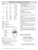
Figure 1
Description
1. Display
2. DATA HOLD/RESET Button
3. Function Dial
4. Positive Jack
5. Negative Jack
6. Continuity Buzzer Sound On/Off
7. AC Voltage
8. DC Voltage
9. Battery test
10. Continuity/Diode
11. Resistance
PROBES
Select either the probe test leads or the clip leads. Plug the red test leads into the
positive “+” jack and the black test lead into the negative “-” jack (4 and 5 Fig. 1).
AUTO-OFF
If the reading has not changed for ten minutes the unit provides warning beeps and
then automatically turns off to conserve battery life. To turn the unit back on and
resume readings press the RESET button (2, Fig. 1).
ACV/DCV/BATTERY/OHM MEASUREMENT
1. Turn the function switch to AC, DC BATTERY, or OHM function
(7, 8, 9, or 11, Fig. 1).
2. Touch or connect leads to the desired circuit and read the display.
CONTINUITY/DIODE MEASUREMENT
1. Turn the function switch to the Continuity/Diode function (10 Fig. 1).
2. Press the Continuity Buzzer Sound On/Off button (6 Fig. 1), until the sound ON
signal is shown on the display “.)))”
3. For Continuity measurement connect the leads across the desired circuit and read
the display. If the impedance of the circuit is less than 20 ohms then the buzzer will
sound.
4. For Diode measurement connect the red test lead to the positive “+” pole of the
diode and the black test lead to the negative “-” pole of the diode. Read the forward
voltage drop on the display.
BATTERY READINGS
1. Turn the function switch to the Battery function (9, Fig. 1).
2. Touch or connect leads to the battery and read the display.
3. Incorporated in the circuitry is a resistive load to test batteries.
HOLD
Press the D-HOLD (Display-Hold) button (2, Fig. 1) to “freeze” the display and capture
a reading. Press it again to release the “freeze” and return to the current reading.
LOW BATTERY
The appearance of the low battery signal, “ ”, erratic readings, a faint display, or no
display are all indicators that the battery is low and needs to be replaced. To prevent
electrical shock, do not remove the battery when the test leads are in place. To
replace the battery, remove the battery cover located on the back of the unit and insert
two new 1.5V batteries with the positive side facing you (Control Company Cat. No.
1039) . Incorrectly installed batteries may damage electronics. Replace the Battery
Cover. To prolong the life of the unit, remove the batteries when the unit is not in use
for an extended period.
ALL OPERATIONAL DIFFICULTIES
If this multimeter does not function properly for any reason, please properly replace
the battery with two new 1.5V batteries (see Low Battery section, above). Low battery
power can occasionally cause any number of “apparent” operational difficulties.
Replacing the battery with a new fresh battery will solve most difficulties.
WARNINGS
Do not exceed 750 volts when in the AC or DC function. Do not exceed 500 volts
when in all other functions. OL on the display means over range. Before testing in
ohms or continuity/diode, OL will be on the display. To avoid electrical shock, never
touch your body to the metal part of the test lead when making a measurement. Do not
use the OHM or Continuity/Diode functions to test voltage. It may damage the meter’s
electronics.
WARRANTY, SERVICE, OR RECALIBRATION
For warranty, service, or recalibration, contact:
CONTROL COMPANY
4455 Rex Road
Friendswood, Texas 77546 USA
Ph. 281-482-1714 Fax 281-482-9448
E-mail sales@control3.com
www.control3.com
Control Company is ISO 9001 Quality-
Certified by DNV and ISO 17025 accredited
as a Calibration Laboratory by A2LA.
TRACEABLE
®
MU
LT
IMET
ER
INSTRUCTIONS