
User guide

Unidrive SP Short Form Guide 15
Issue Number: 2 www.controltechniques.com
Safety
Information
Product
Information
Mechanical
Installation
Electrical
Installation
Getting Started Basic parameters
Running the
motor
SMARTCARD
Advanced
parameters
Diagnostics
UL Listing
Information
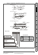
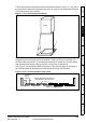
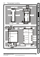
The location and size of the bottom shall cover the area shown in Figure 3-1. Any part of
the side which is within the area traced out by the 5° angle is also considered to be part
of the bottom of the fire enclosure.
Figure 3-1 Fire enclosure bottom layout
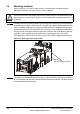
The bottom, including the part of the side considered to be part of the bottom, must be
designed to prevent escape of burning material - either by having no openings or by
having a baffle construction. This means that openings for cables etc. must be sealed
with materials meeting the 5VB requirement, or else have a baffle above.
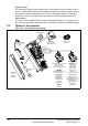
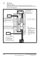
See Figure 3-2 for acceptable baffle construction. This does not apply for mounting in
an enclosed electrical operating area (restricted access) with concrete floor.
Figure 3-2 Fire enclosure baffle construction
Drive
5
o
5
o
Not less
th an 2 X
B affle p la te s (m a y b e
above or below bottom
of enclosure)
X
Bottom of fire
enclosure
Not less
than 2
times ‘X’
Baffle plates (may be above or
below bottom of enclosure)
Bottom of fire enclosure
X