
User guide

Unidrive SP Short Form Guide 33
Issue Number: 2 www.controltechniques.com
Safety
Information
Product
Information
Mechanical
Installation
Electrical
Installation
Getting Started Basic parameters
Running the
motor
SMARTCARD
Advanced
parameters
Diagnostics
UL Listing
Information
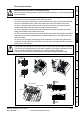
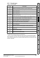
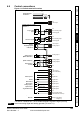
4.5 Encoder connections
Figure 4-5 Encoder
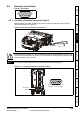
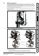
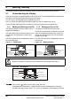
4.5.1 Location of encoder connector (size 0)
Before using the encoder connector on size 0 for the first time, the break-out need
removing as shown in Figure 4-6.
Figure 4-6 Access to encoder connections
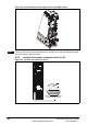
Figure 4-7 Location of encoder connector (size 0)
5
10
15
1
6
11
Break-outs
After removing the break-out, ensure that the ground tab is connected to ground. This
will connect 0V of the drive to ground. This is required to enable the drive to meet IP20
when the break-out is removed.
Do not remove the break-out if the encoder connection is not required.
WARNING
NOTE
5
10
15
1
6
11
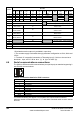
Drive encoder connector
Female 15-way D-type
Encoder
input