
User guide

Unidrive SP Short Form Guide 89
Issue Number: 2 www.controltechniques.com
Safety
Information
Product
Information
Mechanical
Installation
Electrical
Installation
Getting Started Basic parameters
Running the
motor
SMARTCARD
Advanced
parameters
Diagnostics
UL Listing
Information
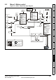
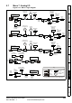
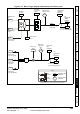
Figure 9-15 Menu 9 logic diagram: Motorized pot and binary sum
9.30
Binary-sum
logic twos
9.29
Binary-sum
logic ones (LSB)
9.31
Binary-sum
logic fours (MSB)
9.32
Binary-sum
logic output
value
??.??
Any
unprotected
bit
parameter
??.??
9.33
Binary-sum
logic
destination
parameter
Σ
9.24
Motorized
pot.
output scale
9.25
Motorized
pot.
destination
parameter
9.23
Motorized
pot. rate
??.??
Any
unprotected
variable
parameter
??.??
9.27
Motorized pot.
down
9.26
Motorized pot.
up
M
9.03
Motorized
pot.
output
indicator
9.22
Motorized
pot. bipolar
select
9.21
9.28
Motorized pot.
reset to zero
Motorized pot.
mode
+
+
9.34
Binary-sum
offset
0.XX
0.XX
Key
Read-write
(RW)
parameter
Read-only (RO)
parameter
Input
terminals
Output
terminals
The parameters are all shown at their default settings
Function disabled if set
to a non valid destination
Function disabled if set
to a non valid destination