
User guide

Unidrive M700 Getting Started Guide 49
Issue Number: 5
Safety information Product information
Mechanical
installation
Electrical installation Getting started Basic parameters
Running the motor
NV Media Card
Operation
Further information
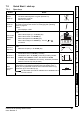
7.2.2 RFC-A mode (with position feedback)
Induction motor with position feedback
For simplicity only an incremental quadrature encoder will be considered here. For information on
setting up one of the other supported speed feedback devices, refer to Setting up a feedback device
in the Unidrive M700 / M701 User Guide.
Action Detail
Before
power-up
Ensure:
• Drive Enable signal is not given (terminal 31)
• Run signal is not given
• Motor and feedback device are connected
Power-up
the drive
• Verify that RFC-A mode is displayed as the drive powers up. If the
mode is incorrect see section section 5.6 Changing the operating
mode
on page 34.
Ensure:
• Drive displays ‘Inhibit’
Set motor
feedback
parameters
Incremental encoder basic set-up
Enter:
• Drive encoder type in Pr 03.038 = AB (0): Quadrature encoder
• Encoder power supply in Pr. 03.036 = 5 V (0), 8 V (1) or 15 V (2).
• Drive encoder Lines Per Revolution (LPR) in Pr 03.034 (set
according to encoder)
• Drive encoder termination resistor setting in Pr 03.039:
0 = A-A\, B-B\, Z-Z\ termination resistors disabled
1 = A-A\, B-B\, termination resistors enabled, Z-Z\ termination
resistors disabled
2 = A-A\, B-B\, Z-Z\ termination resistors enabled
Motor
thermistor
set-up
At factory default, terminal 8 is set-up for an analog voltage input. If a
thermistor is connected to terminal 8, then the Analog Input 3 Mode
(07.015) parameter must be set to Thermistor Short Cct (7), Thermistor
(8) or Therm No Trip (9).
Enter motor
nameplate
details
Enter:
• Motor rated frequency in Pr 00.047 (Hz)
• Motor rated current in Pr 00.046 (A)
• Motor rated speed in Pr 00.045 (rpm)
• Motor rated voltage in Pr 00.044 (V) - check if or connection
Set
maximum
speed
Enter:
• Maximum speed in Pr 00.002 (rpm)
If output voltage from the encoder is >5 V, then the
termination resistors must be disabled Pr 03.039 to 0.
NOTE
Setting the encoder voltage supply too high for the encoder
could result in damage to the feedback device.
CAUT ION
The thermistor input will be disabled until Pr 07.015 is set to
one of the above.
NOTE
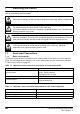
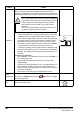
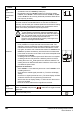
Mot X XXXXXXXXX
No XXXXXXXXXX kg
IP55 I.cl F C 40 s S1
°
VHzmin
-1
kW cos
φ
A
230
400
50 1445 2.20 0.80 8.50
4.90
CN = 14.5Nm
240
415
50 1445 2.20 0.76 8.50
4.90
CN = 14.4Nm
CTP- VEN 1PHASE 1=0,46A P=110W R.F 32MN
I.E.C 34 1(87)
0.02
t