
Setup guide

™
varioushomeautomationactivitiesinComposer
programming.
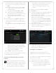
3 Power Button.UsedtopowertheTouchScreen
onoro.See“TouchScreenModes.”
4 Touch Screen.ThefrontfaceoftheTouchScreen.
5 Reset/Restore Pinhole.Usedtoresetorrestore
thefactorydefaults.
6 Speaker.UsedforIntercompurposes.
7 Headphone Jack (3.5 mm).Usedtoconnect
headphonesforintercompurposes.
8 Camera LED Indicator.Indicatesifthecamerais
on.Greenindicatesthecameraison.
9 Power LED Indicator.Indicatesifthepowerison.
10 Microphones.UsedtospeakintotheTouch
ScreenwhenIntercomisused.
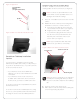
Power and Network Connections
BeforeyoubegintoinstallthisTouchScreen,you’ll
needtomakeafewdecisions:
1 WillyourcustomersbeusingtheTouchScreen
asaportabledevice(docknotattached)orwith
thedockattached?See“PortableorTabletop
InstallationOptions”and“PowerManagement
BestPractices”fordetails.
2 WilltheDCPowerAdapter(included)orPower
overEthernet(soldseparately)beused?See
“PortableorTabletopInstallationOptions”for
details.
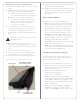
LED Indicators
TheLEDsontheTouchScreenindicatethestatusof
thepowersupply,batterycharge,booting,andsoon,
asdescribedinthenexttable.
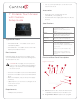
7”Portable
TouchScreen
withCamera
SetupGuide
LED Color Touch Screen Status
O -Notcharging
-Screensavermode,blank
-Screensavermode,charging
Red -O,charging
Green -On,notcharging
-Suspend/asleep,notcharging
Green(blinking) -Booting,notcharging
Green(fastblinks) -Restoring,notcharging
Orange -On,charging
-Suspend/asleep,charging
Orange(blinking) -Bootingwhilecharging
Orange(fast
blinks)
-Restoringwhilecharging
NOTES:(1)IfthedeviceisOFF,pressPower.
Ifthedeviceisasleep,pressanybuttonortap
thescreen.(2)Thedevicemustbeconnected
toapowersupplyforatleastsix(6)hoursso
thebatterycanfullycharge.(3)Ifthebattery
poweriscriticallylow,youcanstillturnonthe
deviceaslongasthedockispluggedintothe
poweradapterorPoE.
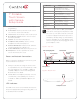
Figure2.TopView
Figure3.BottomView
Headphone Jack
Power/Charging LED
Reset/Restore
Pinhole
Microphones
Camera LED
Power Button
2