
Installation guide
all features as designed. When connected, the
Controller can connect to other IP devices on
the home network and access web-based media
databases and Control4 system updates. For
more information, see the Knowledgebase article
#3 about recommended networking hardware.
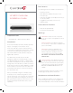
2 Mount options. The HC-800 is designed to be
stackable with other AV equipment or mounted
in a rack or on a shelf using the optional Rack Ear
Kit (C4-1UREK-B, sold separately).
3 Connect the HC-800 to the network. To connect
using an Ethernet connection, plug the data
cable (Ethernet cable or RJ-45 patch cable)
from the home network connection into the
Controller’s RJ-45 port (labeled “Ethernet”) and
the network port on the wall or at the network
switch.
4 Power up the Controller. Plug the HC-800 power
cord (provided) into the Controller’s power plug
port and an electrical outlet.
NOTES: (1) Only use the power supply
included in this box. (2) The HC-800 may
take several minutes to boot up and become
operational. Please allow sucient time for
bootup. This LED blinks Orange and then Blue
during the bootup process.
5 Connect system devices. Attach the devices as
described in “Connect the Devices” below.
6 Set up any external storage devices as described
in “Setting up External Storage Devices.”
Connect the Devices
NOTE: Use Composer Pro to step through
the connection process before or after the
Controller is physically connected.
The following section provides more information
about other connection options.
Pluggable Terminal Block Connectors
For the Contact and Relay ports, the HC-800 makes
use of a pluggable terminal block connector—a
removable plastic part that locks in individual wires
(included).
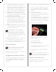
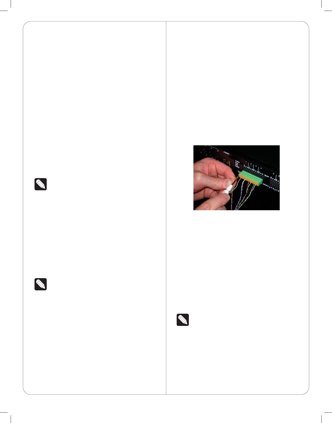
To connect a device to the Pluggable Terminal Block:
1 Insert one of the wires required for your device
into the appropriate opening in the Pluggable
Terminal Block you reserved for that device (see
Figure 3).
2 Insert the wire as follows:
• If using solid core wire, push the wire into the
hole below the slotted retention tab, and ensure
that it’s tightly secured.
• If using stranded wire, push the slotted retention
tab in using a small flat-blade screwdriver. Insert
the wire into the hole below the tab, and then
release the tab to secure the wire (see Figure 3).
Figure 3. Connect to Terminal Block
EXAMPLE: If you add a motion sensor (see
Figure 5), connect its wires to the following
Contact openings:
a Power input to +12V
b Output signal to SIG
c Ground connector to GND
See the following sections for instructions about
connecting the various protocols.
3 Repeat Steps 1 and 2 for all wires required for
your device.
NOTE: If you connect dry contact closure
devices, such as doorbells, connect the switch
between +12V (Power) and SIG (Signal).
Connect to the Contact Port
The HC-800 provides four (4) contact ports for the
pluggable terminal block provided.
4