
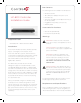
Installation guide
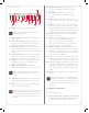
See Figures 4 through 8 to learn how to connect the
device to a contact port.
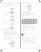
Figure 4. Contact Port for Voltage Source (e.g.,
Motion Sensor)
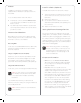
Figure 5. Contact for Dry Contact (e.g., Door Contact
Sensor)
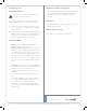
Figure 6. Contact for Self-Powered Voltage Source
Device
Connect to the Relay Port
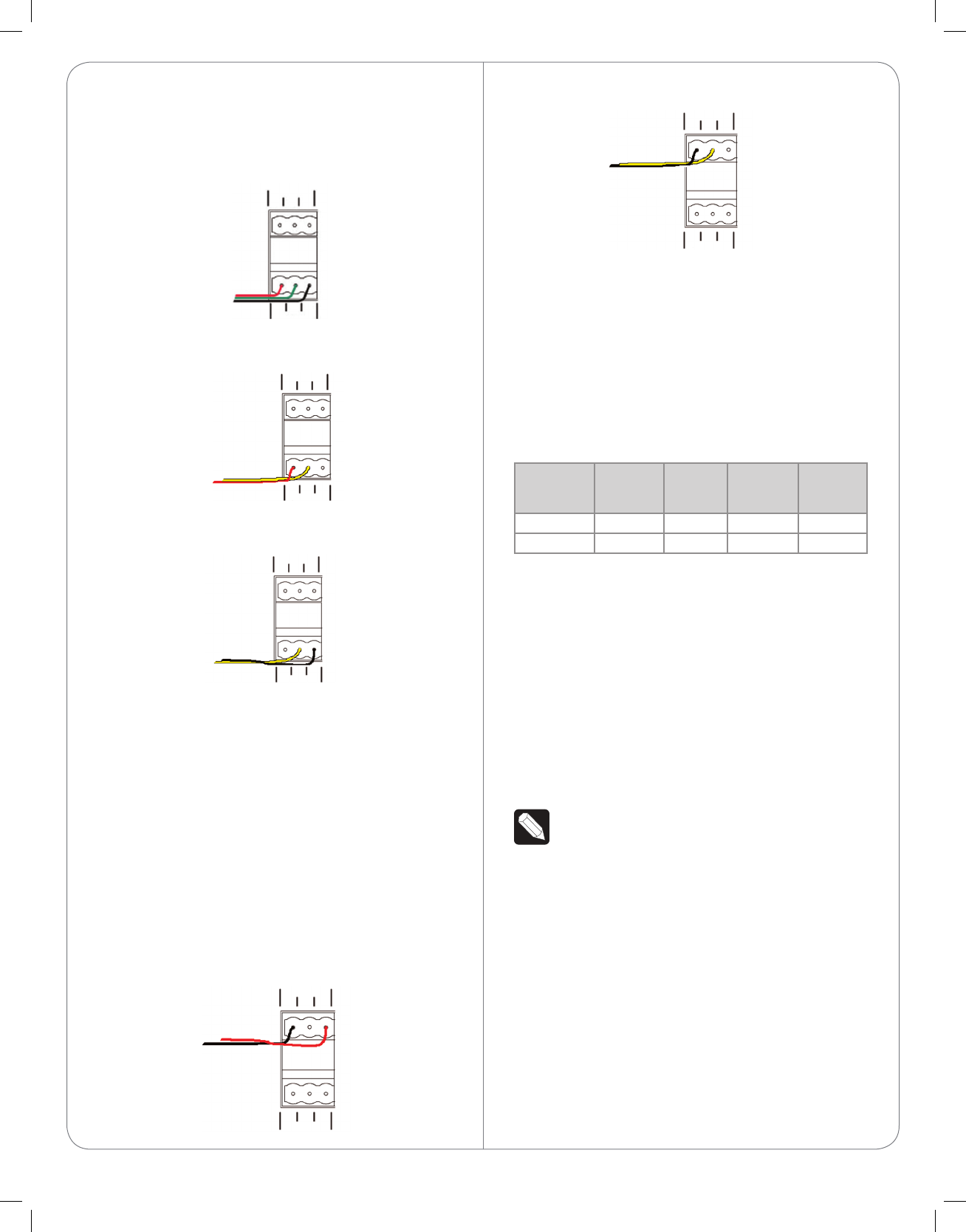
The HC-800 provides four (4) relay ports for the
pluggable terminal block provided. With most
applications, attach one (1) wire to the common
terminal and the other to the Normally Opened
terminal. The relay switches close when the relay is
activated.
The HC-800 can support applications that require a
Normally Closed contact.
Figure 7. Relay Port, Normally Open
Figure 8. Relay Port, Normally Closed
Connect the Serial Ports
The HC-800 has two (2) DB9-style serial ports.
Connect a device, for example, a receiver or disc
changer, to the HC-800 by aligning the pins and
tightening the screws.
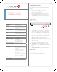
See the next table for serial communication values.
Hardware
Flow
Control
Odd
Parity
Even
Parity
No Parity
Serial Port 1 X X X X
Serial Port 2 X X X X
Set Up IR Emitters or IR Blaster
The system may contain third-party products
that are controlled with IR commands (usually
through remote controls). To provide a way for the
Controller to control a device that only recognizes IR
commands, complete one of these setups for
• IR Emitters
• IR Blaster
NOTE: All IR ports deliver the same amount of
power.
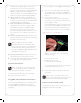
IR Emitters
1 Plug the 3.5 mm connector end of one of the six
(6) IR stick-on emitters provided into an IR Out
port on the HC-800.
2 Place the stick-on emitter end over the IR
receiver on the Blu-ray player, TV, or other target
device to drive IR signals from the HC-800 to the
target.
5
NO
NC
COM
GND
SIG
+12V
RELAYS
CONTACTS
NO
NC
COM
GND
SIG
+12V
RELAYS
CONTACTS
NO
NC
COM
GND
SIG
+12V
RELAYS
CONTACTS
NO
NC
COM
GND
SIG
+12V
RELAYS
CONTACTS
NO
NC
COM
NO GND
SIG
+12V
RELAYS
CONTACTS