
User's Guide
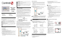
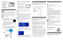
Table Of Contents
- Mini Touch Screen Installation Guide

Mini Touch
Screen
Installation
Guide
Supported Models
Graphical Symbols in this Guide
The following symbols and their descriptions draw your attention to important
safe practices and additional information that can help you avoid injury, death,
or loss of material or time.
WARNING!
This indicates a potentially hazardous situation that, if not avoided,
may result in death or serious injury. DO NOT IGNORE A WARNING!
CAUTION! This indicates a potentially hazardous situation that, if not avoided,
may result in minor or moderate injury. DO NOT IGNORE A CAUTION!
IMPORTANT! This indicates information that will help you avoid damage to
your equipment, loss of materials, or loss of time. PAY ATTENTION TO THESE
IMPORTANT STATEMENTS!
NOTE: This indicates a note on related information about the current topic.
TIP: This indicates a tip that might save you time or effort.
Important Safety Instructions
1. Read these instructions.
2. Keep these instructions.
3. Heed all warnings.
4. Follow all instructions.
5. Do not use this apparatus near water.
6. Clean only with dry cloth.
7. Install in accordance with the manufacturer’s instructions.
8. Do not install near any heat sources such as radiators, heat registers, stoves, or other
apparatus (including amplifiers) that produce heat.
9. Protect the power cords, if applicable, from being walked on or pinched particularly at
plugs, convenience receptacles, and the point where they exit from the apparatus.
10. Only use attachments/accessories specified by the manufacturer.
11. If applicable, unplug this apparatus during lightning storms or when unused for long
periods of time.
12. Refer all servicing to qualified service personnel. Servicing is
required when the apparatus has been damaged in any way, such as power-supply
cord or plug is damaged, liquid has been spilled or objects have fallen into the appara-
tus, the apparatus has been exposed to rain or moisture, does not operate normally,
or has been dropped.
WARNING! To reduce the risk of fire or electrical shock, do not expose this
apparatus to rain or moisture.
WARNING! To avoid bodily harm, always contact a Control4-authorized reseller
for assistance if any repair or adjustment is required.
CAUTION! Do not place unit near sources of heat or expose to direct sunlight
for an extended period of time.
IMPORTANT! Do not use pens or sharp objects to navigate or make selections
on the screen. To select an item or scroll through a list, use either your fingertip or
the Select Dial.
IMPORTANT! Improper use or installation can cause LOSS/DAMAGE OF
PROPERTY.
General Description
An essential component in every Control4 system is a user interface and
navigation method that allows users to communicate with the system. Along
with the Mini Touch Screen, Control4 offers a variety of other navigation options
for every room, including the System Remote Control, On-Screen (television),
10.5” Wireless Touch Screen, etc.
The Control4 Mini Touch Screen offers complete system control in an elegant
and compact design. The Mini Touch Screen is equipped with the touch screen,
an intuitive Select Dial, and a unique programmable shortcut button.
The Mini Touch Screen comes in two models: Ethernet and WiFi. These two
options are described in the following sections.
Mini Touch Screen Placement for both models: Place the Mini Touch
Screen in a convenient location at eye level, typically near the entrace of the
room, approximately 57 to 61 inches from the floor. Note that for the Wireless
model, you need to place it near a power source, such as at an outlet, or be
able to route AC power to it.
Option 1: Ethernet Model
The Ethernet Mini Touch Screen requires a Power over Ethernet (PoE) device
that injects electrical current into the Ethernet cable in order to provide the
Ethernet Mini Touch Screen with both power and a network connection. See
Figure 1. The Ethernet Mini Touch Screen works with the Control4 Power Over
Ethernet Injector (model # AC-POE1-B) or a third-party PoE injector or switch.
If you plan to use a third-party PoE solution or a non-standard connection
cable, refer to “Power Interface Requirements” for the specifications.
Ethernet Placement: Place the PoE Injector near your gateway/router/switch.
Pull the Ethernet cable from that location to the location of where you want to
place your Mini Touch Screen.
FIGURE 1.
Ethernet Model - Requires Ethernet Wiring to Mini Touch Screen.
Option 2: WiFi Model
The WiFi Mini Touch Screen differs from the Ethernet model in two ways:
• It uses a WiFi antenna that communicates via WiFi to a Wireless
Access Point to the Control4 Controller, such as the Home Theater
Controller.
• It gets its power from an AC power source close to the Mini Touch
Screen. This power connection requires both neutral and hot connec-
tions. See Figure 2.
WiFi Placement: Place the WiFi Model above a power source, such as at an
outlet. Ensure you have WiFi in the home.
FIGURE 2.
WiFi Model - Requires AC power to Mini Touch Screen.
IMPORTANT! If you already have a network setup distributing DHCP, manually
disable any DHCP service on any device you add prior to putting it on the
network, such as a wireless router. You cannot have two devices running DHCP
or this may result in devices malfunctioning. For information about setting up a
home network, see Composer online help topic: “Guidelines for Setting up a
Wired or Wireless Network.”
Wall Box Kit Options
There are four wall box options to install the Mini Touch Screen. Metal and
plastic wall boxes are available for new or retrofit versions. The following
diagrams show the available wall mounting kits.
FIGURE 3.
Mini Touch Screen/LCD Keypad Wall Box Kits - New Construction
FIGURE 4.
Mini Touch Screen/LCD Keypad Wall Box Kit - Retrofit (includes wall
box template)
What’s in the Box
Carefully unpack the contents from the box and make sure the following items
are included in the box. If any item is missing or damaged, please contact your
Control4-authorized reseller immediately.
• Control4 Mini Touch Screen
• Warranty card
• Mini Touch Screen Installation Guide (this document)
• Mini Touch Screen User Guide
• Two sheet metal screws (1/2 inch) for attachment to a plastic wall box.
(Metal wall boxes require machine screws. They are included with the
the metal wall box kit.)
Requirements
To install the Mini Touch Screen, you need the following:
• Home Theater Controller or Media Controller fully installed and config-
ured with a Control4 system.
• (Optional) An amplifier or amplified speakers.
• (Optional) Any RCA cables required to connect the Mini Touch Screen
and the amplifier or amplified speakers.
• Ethernet only:
• Ethernet network installed and available that includes a gateway/
router/switch.
• Control4 PoE Injector (model #AC-POE1-B) or another third-party PoE
injector or switch.
• Two Ethernet Category 5 cables to support your PoE injector: (1) one
that will run from the Ethernet gateway/router/switch to the PoE
injector/switch and (2) one that will run from the PoE injector/switch to
the Ethernet Mini Touch Screen wall box.
• WiFi only:
• Wireless network (WiFi 802.11b/g) installed and available that includes
a wireless access point (WAP).
• Access to in-wall AC power. (A neutral connection is required).
• 14 AWG electrical wire long enough to pull between Mini Touch
Screen and power source.
• Control4 Mini Touch Screen/LCD Keypad custom wall box kit. See
“Wall Box Kit Options.”
Front and Rear Panel Description
Front View
1. Microphone: (Future) Microphone
for communication features.
2. Speaker: (Future) Speaker for inter-
com.
3. Select Dial: Use during setup to iden-
tify the device to the Control4 system.
Once setup is complete, for scrolling
through displays.
4. Shortcut Button: For custom pro-
gramming to initiate an action or
sequence of actions.
5. Display: 3.8" TFT (3.5” viewing area), Touch-Screen with 320x240 Resolution,
QVGA.
Back View: Ethernet Model
1. RCA audio line-level output:
(Optional) Connect these ports to an
amplifier or amplified speakers for audio
output using a standard RCA stereo
cable.
2. RJ-45 port: For connection to the Ether-
net PoE source to power the device and
provide network communication.
3. Dimension: Front - 6 1/2” (W) x 4 3/8”
(H) x 1/5-2/5” (D)
4. In-Wall - 5 7/8” (W) x 3 5/8” (H) x 1 1/2”
(D)
5. Power Supply: PoE (Power Over Ethernet).
Ethernet Models:
TSE-3.8C1-W (White)
TSE-3.8C1-B (Black)
TSE-3.8C1-A (Almond)
WiFi Models:
TSG-3.8C1-W (White)
TSG-3.8C1-B (Black)
TSG-3.8C1-A (Almond)
Plastic model # AC-NWB3.8-G Metal model # AC-NWB3.8-M
Plastic model # AC-RWB3.8-G Metal model # AC-RWB3.8-M