
Installation Guide
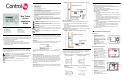
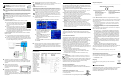
Table Of Contents
- Mini Touch Screen Installation Guide
- Supported Models
- What’s in the Box
- Graphical Symbols in this Guide
- Important Safety Instructions
- Placement and Model Options
- Wall Box Kit Options
- Requirements
- Front and Rear Panel Description
- Wall-Mounted Installation
- Power Interface Requirements - Ethernet
- Troubleshooting
- Regulatory Compliance
- About this Document

Wall-Mounted Installation
WARNING! For the location where you are installing the Mini
Touch Screen, switch off the circuit breaker or remove the fuse
from the fuse box.
IMPORTANT! For new or retrofit, when cutting the opening for
the wall box, DO NOT cut the opening too large. Be conservative and cautiously
enlarge it as needed because there is not as much overhang on the faceplate of
the Mini Touch Screen as you are accustomed to with standard switch and outlet
plates.
IMPORTANT! Before you can complete the installation instructions for the Mini
Touch Screen, you must have a Control4 Mini Touch Screen\LCD Keypad Wall
Box installed according to the documentation provided in the wall box kit.
NOTE: These installation instructions do not apply to Table-Top Box installations.
For Table-Top Box installations, refer to the installation documentation that ships
with the table-top box kit.
1 Prepare wall for installation.
For Ethernet Model: Install a PoE injector or switch. To do this:
a. Connect the Control4 PoE Injector to a power source,
such as an AC outlet, using the power cord (provided
with the unit). The light comes on when power is
applied.
b. Connect one of the RJ-45 LAN ports on the gateway/
router/switch to the PoE Injector’s LAN port using the RJ-45 ethernet
cable. The STAND BY light on the PoE Injector lights up.
c. Connect the PoE Injector’s PWR LAN-OUT port to the Ethernet Mini
Touch Screen using the RJ-45 ethernet cable in the wall. The Power
mode LED will change from orange to green.
For Wireless Model: Connect wires to AC Power Source for Wireless
Model. To do this:
a. Connect the black (hot) and white (neutral) wires from the back of
the Mini Touch Screen to the hot and neutral wires from the wall.
b. Cap the ground wire from the wall if you are using a plastic wall box.
If you are using a metal wall box, attach the ground wire to the box at
the location designated by the ground symbol.
2 (Optional) If you intend to send audio to an amplifier or amplified
speakers, route a stereo RCA cable from your Mini Touch Screen audio
out ports (RCA red and white connectors) to your amplifier or amplified
speakers.
3 With the screws provided, attach the
Mini Touch Screen base at the top-left
and bottom-right corners of the wall box
(as shown).
4 Hook the tabs on the left underside of
the faceplate onto the lip of the base on
the left-hand side. Then close the
faceplate over the top of the base from
left to right, feeding the Select-Dial post through the corresponding hole in
the faceplate.
5 Install the washer and the nut to hold the faceplate in place.
IMPORTANT!
Tighten the nut by hand. Do not overtighten. Excessive force will
permanently damage the rotary device and void the warranty.
6 Install the Select Dial on the post.
TIP:
You need to calibrate your Mini Touch Screen: the first time you use it or any
time the system requests it. When the device needs calibration, the on-screen
instruction will prompt you to calibrate the device. To do this, use your fingertip to
touch the screen firmly and accurately at the point indicated by the crosshairs.
Repeat for each of the four subsequent points indicated by the crosshairs
NOTE: To protect the display screen of your device: (1) Use one of the screen-
saver options available from the
Info > Config > Screen Saver page; (2) Use a
plastic (cling-on) screen protector (available where hand-held electronic devices
are sold) to help guard against scratches.
7 (For WiFi Model only) From the WiFi Mini Touch Screen, connect to a
wireless access point:
a. Press Info > Wireless > Wireless. The Wireless configuration
screen appears.
b. Press Add to add the WiFi Mini Touch Screen as a wireless device.
c. Press in the Network (SSID) text box
to enter the SSID. A virtual keypad
displays for you to enter the
information.
d. Press the WEP button, then enter the
WEP key in hex in the text box. A
virtual keypad displays for you to enter
the information. Press OK when
finished.
e. Highlight the SSID of the WiFi Mini Touch Screen and press Enable.
f. Press OK.
8 Now that your Mini Touch Screen is physically installed and appearing on
the home network, you can add it to the Control4 System using the
Composer software (available for your PC). See Composer online help for
information on how to add the Mini Touch Screen and other devices to the
Control4 System.
Power Interface Requirements - Ethernet
Ethernet Models
Only: If you plan to
use any other PoE
solutions besides
the Control4 PoE
Injector, such as a
third-party injector
or PoE switch, then
refer to the
Ethernet Mini
Touch Power
Interface diagram
to determine how
to create a PoE
solution and
cabling to meet the
power and
connection
requirements for
Mini Touch Screen.
Troubleshooting
If you experience operational problems with the Control4 Mini Touch Screen,
check the following list for system troubleshooting. If problems persist, contact
your authorized Control4 dealer for technical support.
Question: What if the on-screen display that reads “Welcome to Navigator” won’t go
away?
Answer: If screen also has text that reads “Touch the crosshairs firmly...,” then you
need to calibrate the device as described in the installation instructions.
Question: What if my Mini Touch Screen locks up or runs slowly?
Answer: Try rebooting by holding down the Select Dial for ten seconds. Reset the
system by cutting and restoring power: for Ethernet model, disconnect and reconnect
the PoE connector at the network gateway, router or switch.
Question: What if my Mini Touch Screen is damaged?
Answer: Contact your Control4-authorized reseller.
Question: What if I have network connection problems?
Answer: Make sure the network cable connectors are firmly locked into the network
jack. See Composer online topic: “Guidelines for Setting up a Wired or Wireless
Network.”
Question: What if my Mini Touch Screen is unresponsive to the touch?
Answer 1: The nut under the Select Dial may be too tight. This can cause the
faceplate to press against the overlay causing a false “press and hold” and renders
the touch overlay inoperable. To fix this, loosen nut until proper operation is restored.
Answer 2: The Mini Touch Screen may need to be recalibrated. Call technical support
for further information on this procedure.
Regulatory Compliance
This product complies with standards described in this section that were
established by North America, Europe, and Australia/New Zealand regulatory
bodies.
FCC Interference Statement
This equipment has been tested and found to comply with the limits for a Class
B digital device, pursuant to Part 15 of the FCC Rules. These limits are
designed to provide reasonable protection against harmful interference in a
residential installation. This equipment generates, uses, and can radiate radio
frequency energy and, if not installed and used in accordance with the
instructions, may cause harmful interference to radio communications.
However, there is no guarantee that interference will not occur in a particular
installation. If this equipment does cause harmful interference to radio or
television reception, which can be determined by turning the equipment off and
on, the user is encouraged to try to correct the interference by one or more of
the following measures:
• Reorient or relocate the receiving antenna.
• Increase the separation between the equipment and receiver.
• Connect the equipment into an outlet on a circuit different from that to
which the receiver is connected.
• Consult the dealer or an experienced radio/TV technician for help.
FCC Caution
IMPORTANT!
Any changes or modifications not expressly approved by the
party responsible for compliance could void the user's authority to operate the
equipment.
This device complies with Part 15 of the FCC Rules. Operation is subject to the
following two conditions: (1) This device may not cause harmful interference,
and (2) this device must accept any interference received, including
interference that may cause undesired operation.
Industry Canada Statement
This Class B digital apparatus complies with Canada ICES-003.
Cet appareil numérique de la classe B est conforme à la norme NMB-003 du
Canada.
Underwriters Laboratories Inc. (UL)
This product has been tested by UL and has been found to
be in compliance with:
UL 916:1998: Standard for Energy Management Equipment
European Compliance
-----------------------------------------------------------------------------------------------------
CE Declaration of Conformity
Product: MiniTouch Screen, Models: See “Supported Models” on page 1.
The undersigned hereby declares, on behalf of Control4 Corporation, that the
above-referenced product, to which this declaration relates, is in conformity
with the provisions of:
• Council Directive 89/336/EEC (May 3, 1989) on Electromagnetic Compatibility
• Council Directive 1999/5/EC (Mar 9, 1999) on Radio & Telecommunication Ter-
minal Equipment (R&TTE)
• Council Directive 73/23/EEC (Feb. 19, 1973) on Low Voltage Equipment Safety
• Council Directive 93/68/EEC (Jul. 22, 1993) Amending Directives 89/336/EEC
and 73/23/EEC
and has been tested to the requirements of, and shown to be in compliance
with, the following requisite standards:
• EN 301 489-1 V1.4.1 - Electromagnetic compatibility and Radio spec-
trum Matters (ERM); ElectroMagnetic Compatibility (EMC) standard for
radio equipment and services- Part 1 Common technical requirements.
• EN 301 489-17 V1.2.1 - Electromagnetic compatibility and Radio spec-
trum Matters (ERM); ElectroMagnetic Compatibility (EMC) standard for
radio equipment and services; Part 17: Specific conditions for 2,4 GHz
wideband transmission systems and 5 GHz high performance RLAN
equipment.
• EN 300 328-V1.4.1 (2003-04) - Wide band transmission systems; data
transmission equipment operating in the 2.4GHz ISM band. Harmon-
ised EN covering essential requirements under Article 3(2) of the R &
TTE Directive.
• EN60950-1: 2001.
• IEC60950-1: First Edition 2001 Including CB Scheme Group &
National Differences as detailed in CB Bulletin 107A May 2004.
The Technical Construction File required by these Directives is maintained at
the corporate headquarters of Control4, Salt Lake City, Utah, U.S.A.
Signed,
Paul E. Nagel—Vice President of Engineering, January 4, 2007
-----------------------------------------------------------------------------------------------------
Australian/New Zealand Compliance
This product has been tested to the requirements of, and shown to
be in compliance with, the following requisite standards:
• AS/NZS60950-1: 2003
Recycling
For information on recycling, please go to www.control4.com/
recycling
About this Document
United States Patents Pending. Copyright © 2004-2007 Control4 Corporation.
Control4 and the Control4 logo are registered trademarks of Control4
Corporation. All trademarks are properties of their respective owners.
Part Number: 200-00010 Rev D
European Contact Information
Control4 UK Limited
Unit 3, Green Park Business Centre
Sutton-on-the-Forest, York
YO61 IET, United Kingdom
+44 (0) 134781 2300
c4@control4-UK.com
United States Contact Information
Control4 Corporation
11734 S. Election Road, Suite 200
Salt Lake City, UT 84020-6432, USA
Tel (801) 523-3100