
User's Manual
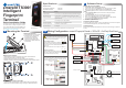


Wiring Configuration: emerald TS300f + DIU200 + S610s SE
3b
LK5
LK4
LK7
S610s SE Reader
(Serial)
H0
J5
J15
H1
485 A
485B
GND
J6
J7
J3
J10
Keypad
485A
485B
GND
+
LNK 2
LNK 3
LNK 4
LNK 5
1
2
4
8
J1
J5
GPO
COM
REX
DOOR
COM
LOCK
J9
J8
BGU
COM
FIRE
TAMPER
BUZZ –
BUZZ +
COM
485A
485B
RDR +12
J2
LOCK –
COM
MAINS FAIL
LOCKIN 12V/24V
SUPPLY 12V
LOCK +
J4
J3
DIU200
J30
JMP1
SW2
12VGND
J10
J11
SAFETY GND
OV
RS232 RX
SOUNDER
LED GREEN
LED AMBER
0V
LED RED
D0
INT EXT
INT EXT
DRY CONTACT RELAY OUTPUTS: 0-24V DC @ 2A (EXTERNAL SUPPLY)
WET CONTACT RELAY OUTPUTS: 12V DC NOW @ 13A (INTERNAL SUPPLY)
D1
DOOR POS
REX
1 RS485 A
1 RS485 B
RS232 TX
0V
3 RS485 A
3 RS485 B
12V 12V0V NO
RELAY 1
C
C
NC
NC
0V 0V
NO
INTERLOCK
LOCK POS
RELAY 2
J19 J17
J18
DOOR
POSITION
LOCK
SENSE
REQUEST
TO EXIT
NOTE:
On the DIU, if BGU, FIRE and TAMPER are not used the
connections on J9 must be linked out.
BGU
COM
FIRE
TAMPER
BUZZ –
BUZZ +
BGU
COM
FIRE
TAMPER
BUZZ –
BUZZ +
BGU
COM
FIRE
TAMPER
BUZZ –
BUZZ +
FIRE
BGU
TAMPER
MAGNETIC
LOCK
-
+
PSU 12V
2A min
-
+
J1
LABEL
Ferrite -
Double
Loop
micro
SD card
For more information on emerald TS300f, consult the following resources.
Datasheets
http://www.cemsys.com/emerald
Installation Manual http://www.cemsys.com/support
User Guide http://www.cemsys.com/support
Technical Support
Tel: +44 (0)28 90 456656
Sales
cem.sales@tycoint.com
1. On the terminal home screen swipe across the Date/Time area from left to right.
Setting the terminal IP address, SubNet mask and Gateway
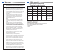
Checking Network Status
1. Press and hold the Reader Address to show the network status indicator.
Terminal has received the onboard database
Terminal has received
configuration settings
from the CDC
Terminal is connected to network via Ethernet
Terminal is connected
to the RTC
Configuring the Network
5
The terminal is now connected to the AC2000 system and ready to use.
4. Select the IP address field, enter the address and press OK.
5. Press the SubNet mask field, enter address and press OK.
6. If necessary, select the Gateway field, type the address and press OK.
7. Press Done to close the Network menu.
!
!
WARNING This is a class A product. In a domestic environment this product may
cause radio interference in which case the user may be required to take
adequate measures.
Installation of this device should be performed by a qualified person in accordance
to all local regulations. See the emerald Installation Manual for safety information.
2. Enter the passcode 67679999 to access the Config Menu.
Note: When the terminal has received a configuration from the server the pass
code changes to 67670000.
3. Press Device settings | Network
Safety and Regulatory Information
Support
Copyright © 2015 Controlled Electronic Management Systems Limited. All rights reserved.
No part of this publication may be produced without the written permission of CEM Systems Limited.
4
Re-assembling the Terminal
Ensure there is adequate network cable length to reach the connectors.
Care should be taken when re-assembling the unit. The front case should
not be left hanging from the ribbon cable while attached to the back case.
1. Connect the ribbon cable to the I/O board.
Note: Power is supplied via the DIU PSU
3. Screw the front casing to the back
casing using the four security hex screws.
4. Clip the side panels on to each side of
the terminal covering each of the
mounting screws.
2. Attach the front case to back case ensuring
the ribbon cable folds below connector J18.