
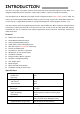
User Manual


4
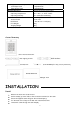
Attach the unit to the back cover.
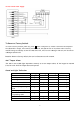
Wiring
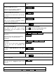
Wire Color Function
Notes
Basic Standalone Wiring
Red AC&DC 12~24V DC/ 12-18V AC Regulated Power Input
Black AC&DC 12~24V DC/ 12-18V AC Regulated Power Input
Pink GND Negative Pole
Blue NO Normally Open Relay output
Purple COM Common Connection for Relay output
Orange NC Normally closed Relay Output
Yellow OPEN Request to Exit Button
Advanced Input and Output Features
Green D0 Wiegand Input/Output Data 0
White D1 Wiegand Input/Output Data 1
Grey Alarm - Alarm Negative
Brown D_IN Door status detecting
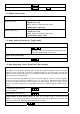
Connection Diagram
Common Power Supply