THE 402 OPERATOR AND 455 D CONTROL PANEL: INSTALLATION MANUAL November, 2003 402 Operator And 455 D Control Pa nel Installation Manual CONTENTS 2 Technical Data 4 Unpacking the Operator 5 The 402 Compact Operator General Characteristics 6 Installation Instructions 6 Prepare the Gate 6 Manual Release Mechanism 7 Install the Operator 7 Install the 455 D Control Panel 9 Exploded View, 402 CBC 11 402 Parts List 12 The 455 D Control Panel Installation Instructions Important Safety Informa
November, 2003 402 Operator And 455 D Control Pa nel Installation Manual P a ge 2 I MPORTANT S AFETY I NFORMATION Both the installer and the owner and/or operator of this system need to read and understand this installation manual and the safety instructions supplied with other components of the gate system. This information should be retained by the owner and/or operator of the gate. WARNING! To reduce the risk of injury or death 1. 2. R E AD AND FOLLOW AL L I N S TR U C TI O N S .
November, 2003 402 Operat or And 455 D Control Pa nel Installation Manual P a ge 3 6. It is extremely unsafe to compensate for a damaged gate by increasing hydraulic pressure. • Do not install or operate the equipment with bare feet. 7. Devices such as reversing edges and photobeams must be installed to provide better protection for personal property and pedestrians. Install reversing devices that are appropriate to the gate design and gate application.
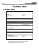
November, 2003 402 Operator And 455 D Control Pa nel Installation Manual P a ge 4 TECHNICAL DATA THE 402 COMPACT OPERATOR Parameter 402 Operator Physical dimensions: Weight, lb (kg) 14-1/3 (6.5) Length, in. (mm) 36 (914) Width ´ height, in.
November, 2003 402 Operat or And 455 D Control Pa nel Installation Manual P a ge 5 UNPACKING When you receive your 402 Compact Operator, complete the following steps. Inspect the shipping box for physical damage such as leaking oil or a torn carton. Then inspect the operator after you remove it from the box. Notify the carrier immediately if you note any damage because the carrier must witness the damage before you can file a claim.
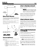
November, 2003 402 Operator And 455 D Control Pa nel Installation Manual P a ge 6 THE 402 COMPACT OPERATOR GENERAL CHARACTERISTICS leaf gate system, the operating logic for your gate system, the pause time, the reversing stroke, and the behavior of reversing devices. The 402 Compact Operator is an automatic, light-duty gate operator it can accommodate a gate leaf up to 10 ft (3m) in length and up to 900 lbs (410 kg) in weight. Note: The 402 Compact Operators recommended for use with solid gates.
November, 2003 402 Operat or And 455 D Control Pa nel Installation Manual P a ge 7 ATTACH THE REAR MOUNTING BRACKET Attach the rear mounting bracket according to the dimensions in Figure 4. WARNING! You must achieve the A and B dimensions, dimensions as specified in Figure 4. Modification of the rear bracket may be necessary to achieve these dimensions (I.e., cutting or extending the bracket provided) Figure 2.
November, 2003 402 Operator And 455 D Control Pa nel Instal lation Manual P a ge 8 as instructed below, will ensure proper location of the front mounting bracket. Bolt or weld the front mounting bracket to the marked location on the gate. WARNING! Do Not Weld the front mounting bracket with the operator attached. Doing so will seriously damage the operator.
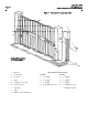
November, 2003 402 Operat or And 455 D Control Pa nel Installation Manual P a ge 9 Figure 6. INSTALLING THE 455 D CONTROL PANEL Locate the control panel in the most convenient position possible, considering the movement of the gate. Figure 6 shows a basic layout for a two-leaf gate with the 402 Compact Operator.
November, 2003 402 Operator And 455 D Control Pa nel Installation Manual P a ge 1 0 Figure 7.
November, 2003 402 Operat or And 455 D Control Pa nel Installation Manual EXPLODED VIEW, 402 CBC P a ge 1 1
November, 2003 402 Operator And 455 D Control Pa nel Installation Manual P a ge 1 2 402 PARTS LIST POS PART NO.
November, 2003 402 Operat or And 455 D Control Pa nel Installation Manual THE 455 D CONTROL PANEL: INSTALLATION MANUAL PAGES 14— 25 P a ge 1 3
November, 2003 402 Operator And 455 D Control Pa nel Installation Manual THE 455 D CONTROL PANEL INSTALLATION INSTRUCTIONS P a ge 1 4 THE 455 D CONTROL PANEL GENERAL DESCRIPTION The FAAC 455 D control panel is used to operate the following models. and for making sure that the entire gate system meets all applicable electrical codes. The installer should refer to the installation manual for a given operator for more information. NOTE: An installation is U.L.
November, 2003 402 Operat or And 455 D Control Pa nel Installation Manual P a ge 1 5 connect the white wire to terminal 4 (on the J4 terminal strip), the black wire to 5, the red wire to 6. Wire each leg of the capacitor (supplied) to terminals 5 & 6. WARNING! Turn the main power off before CHECK THE MOTOR’S DIRECTION OF ROTATION you make any electrical connections or before programming. CAUTION: The operators are grounded only by the grounded circuit the installer provides.
November, 2003 402 Operator And 455 D Control Pa nel Installation Manual P a ge 1 6 N 22 23 24 25 L 2 3 4 5 6 7 C OM OP C L C OM OP C L 115 V A C +/- 10% or 230 V A C +6/ -10% 50-60 Hz C1 M1 8 9 10 11 12 13 14 15 16 17 18 19 C L OP LA MP - - - FS W MOTOR 2 BLUE MOTOR 1 BLUE THE 455 D CONTROL PANEL INSTALLATION INSTRUCTIONS 1 + + 24V FS W 20 21 W .LIGHT LOCK E LE CTRIC LOCK C2 24 vdc 3W M2 OP E N Figure 9.
November, 2003 402 Operat or And 455 D Control Pa nel Installation Manual P a ge 1 7 (b) U.L. Listed Control Panel Enclosure To the U. L. Listed gate operator (a) U.L. Listed cord grip 455 D Control Panel Junction box High-voltage terminal strip Legend White J3 Red Black Yellow/ Green To the U.L. Listed control panel J4 J1 COM OP CL COM OP CL Ground Conduit to U.L. Listed control panel enclosure according to N.E.C.
November, 2003 402 Operator And 455 D Control Pa nel Installation Manual THE 455 D CONTROL PANEL INSTALLATION INSTRUCTIONS P a ge 1 8 opening and closing, respectively, are triggered. Use the LEDs and the next table to determine if the accessory devices you have installed are operating properly. Electric Locks: An electric lock can be wired to the 455 D in terminals 18 and 21 (12Vac pulsed provided). • command to open and a command to close. A second command during opening stops the gate.
November, 2003 402 Operat or And 455 D Control Pa nel Installation Manual P a ge 1 9 Magnetic Lock + Lock 17 9 NO 14 14 C 18 12 vac Relay N.C. N.O. 21 COM Shadow Loop FAAC Rev ersing Photocells (f or opening) Additional Reversing Devices 1 TX 2 19 17 C 12 NC Coil Voltage = Motor Voltage Additional Reversing Devices 1 13 19 N.C. 2 14 N.O.
November, 2003 402 Operator And 455 D Control Pa nel Installation Manual P a ge 2 0 THE 455 D CONTROL PANEL INSTALLATION INSTRUCTIONS PROGRAMMING BASIC PROGRAMMING To program the automated system, “Programming Mode” must be accessed. Programming is split into two parts: ADVANCED. F the BASIC and Display Function Default OPERATING LOGICS BASIC PROGRAMMING To access BASIC PROGRAMMING, press the “F” key. • If you press it (and hold it down), the display shows the name of the first function.
November, 2003 402 Operat or And 455 D Control Pa nel Installation Manual P a ge 2 1 ADVANCED PROGRAMMING + + F INDICATOR-LICHT: Default MAXIMUM TORQUE AT INITIAL THRUST: The motors operate at maximum torque (ignoring the torque setting) at start of movement. Useful for heavy leaves. 4 = Enable No = Disabled LAST STROKE AT CLOSING: The motors are activated at full speed for 1s to facilitate locking of the electric lock.
November, 2003 402 Operator And 455 D Control Pa nel Installation Manual P a ge 2 2 THE 455 D CONTROL PANEL INSTALLATION INSTRUCTIONS LEARNING OF OPERATING TIMES • WARNING: During the learning procedure, the safety devices are disabled! Therefore, any and all traffic must be avoided in the path of the gate leaf(s). • NOTE: Programming must start with the gate(s) in the closed position.
November, 2003 402 Operat or And 455 D Control Pa nel Installation Manual • COMPLETE LEARNING NOTES: • • • If only one gate operator (1) is used, you must go through the entire programming procedure, as if you were programming a gate operator (2). When the gate operator (1) has finished opening, supply 5 open commands until the gate operator begins to close, and then resume normal operations.
November, 2003 402 Operator And 455 D Control Pa nel Installation Manual P a ge 2 4 THE 455 D CONTROL PANEL INSTALLATION INSTRUCTIONS A (Automatic) Logic (455 D) Gate Status Open A Open B Stop Opening Reversing Device(s) Closing Reversing Device(s) Warning Light Closed Opens both leaves and closes them after pause time Opens single leaf connected to Motor 1 and closes it after pause time No effect No effect No effect Off No effect On Opening No effect No effect Stops Stops; gate close
November, 2003 402 Operat or And 455 D Control Pa nel Installation Manual P a ge 2 5 E (Semi-automatic) Logic (455 D) Open A Open B Stop Opening Reversing Device(s) Closing Reversing Device(s) Warning Light Closed Opens both leaves Opens single leaf connected to Motor 1 No effect No effect No effect Off No effect On Opening Stops Stops Stops Stops; gate closes when reversing device no longer triggered Opened Closes both leaves Closes leaf Stops No effect No effect (opening is inhi
November, 2003 402 Operator And 455 D Control Pa nel Ins tallation Manual P a ge 2 6 MAINTENANCE THE 402 OPERATOR Light duty use: every 12 mo The FAAC recommended maintenance schedule varies according to the frequency of use of the operators, whether lightly used operators (once or twice an hour) or heavily used operators (many cycles per hour), operators used in a humid, salt air climate should follow the heavy duty use schedule. CHECK SAFETY • • • • CHANGE IN THE OIL.
November, 2003 402 Operator And 455 D Control Pa nel Installat ion Manual P a ge 2 7 TROUBLESHOOTING WARNING! Before you do any work on the control panel, be sure to turn off the main power. PROBLEM: THE GATE DOES NOT OPEN COMPLETELY. PROBLEM: THE RADIO CONTROLLED OPENER DOES NOT OPEN THE GATE. SOLUTION: SOLUTION: Check the gate for mechanical obstacles that might prevent the gate from opening. Check the light on the front of the remote transmitter. It should illuminate when you signal the gate.
November, 2003 402 Operat or And 455 D Control Pa nel Installation Manual P a ge 2 8 LIMITED WARRANTY To the original purchaser only: FAAC International, Inc., warrants, for twenty-four (24) months from the date of invoice, the gate operator systems and other related systems and equipment manufactured by FAAC S.p.A. and distributed by FAAC International, Inc.